Maxwell J. Toms
49 Julian Street, Carleton Place, Ontario, Canada, K7C 3W7
mjtoms@sympatico.ca (613) 257-7290
Building a replica 9-Pounder, Part 2, The Limber
This project came about as a result of my commentary to Scout Leader Terry Honour regarding his efforts to provide adequate looking artillery for the War of 1812-14 re-enactments undertaken by his and other scout troops every September at Fort George, Niagara, Ontario. Since Terry’s troop had adopted the Royal Newfoundland Regiment colours, the Fencibles, I was ‘honour’ bound, pun intended, to help.
I was surprised to learn the contribution by the early Newfoundland Regiment, in these battles, both in the skill, dedication and resourcefulness, earning honourable mention by British Officers on many occasions.
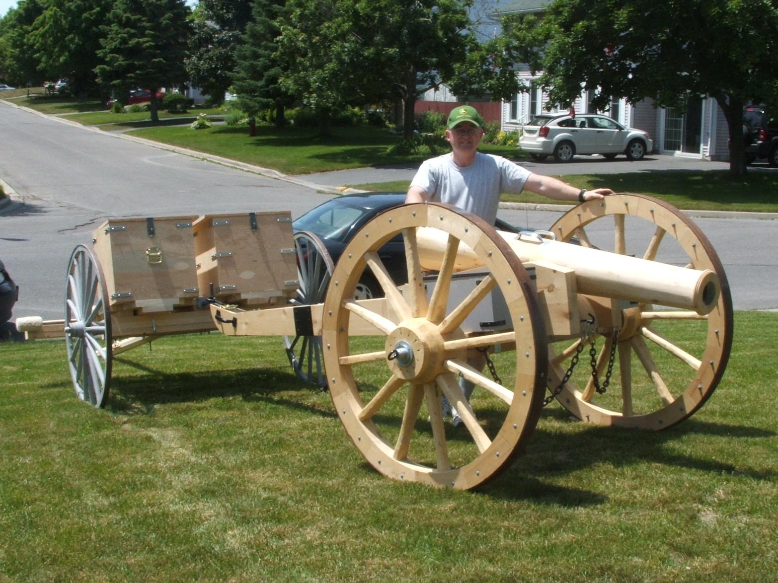
The Mission: Build a replica artillery
piece suitable for War of 1812-14 re-enactments
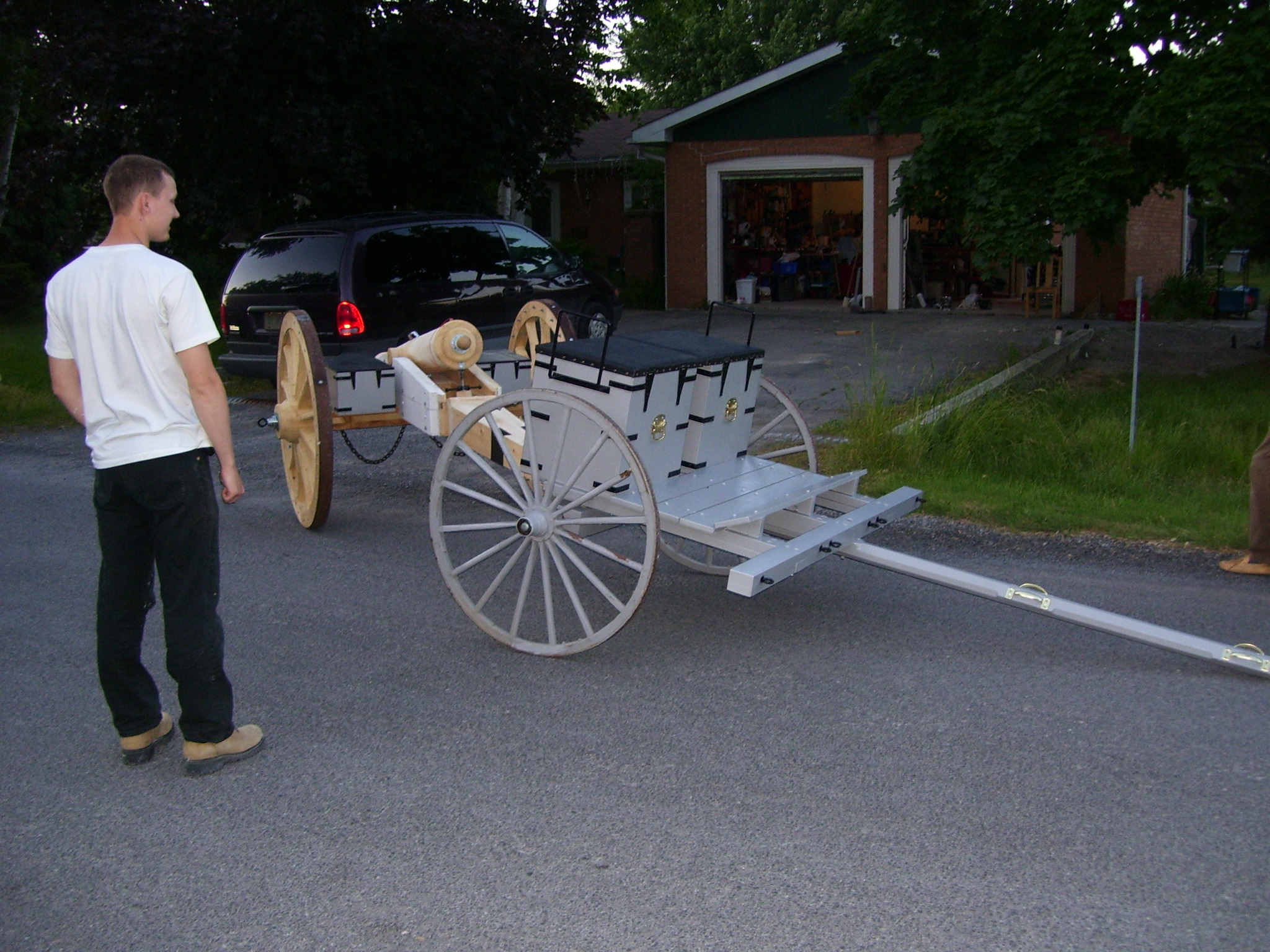
The field piece needed to look approximately like a limber for the 9-pounder Napoleonic Cannon of the period, which had to be able to simulate firing. We could only use inexpensive materials we could get from the local hardware stores. The gun and limber had to be light weight and easily disassembled for storage and transport.
There was no attempt to make a museum piece, but rather a reasonably correct looking gun & limber that could be easily manoeuvred and safely fired by the Scouts & Venturers.
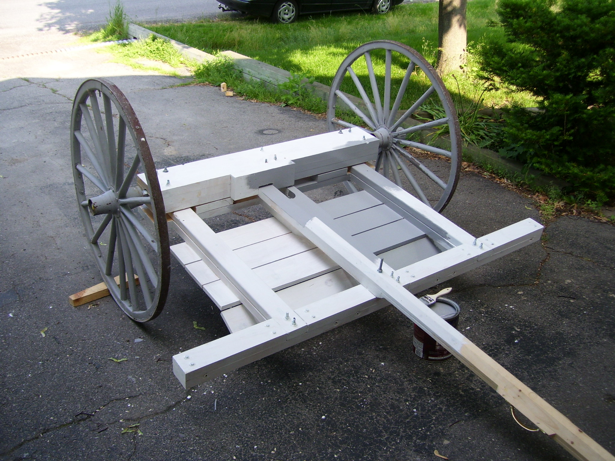
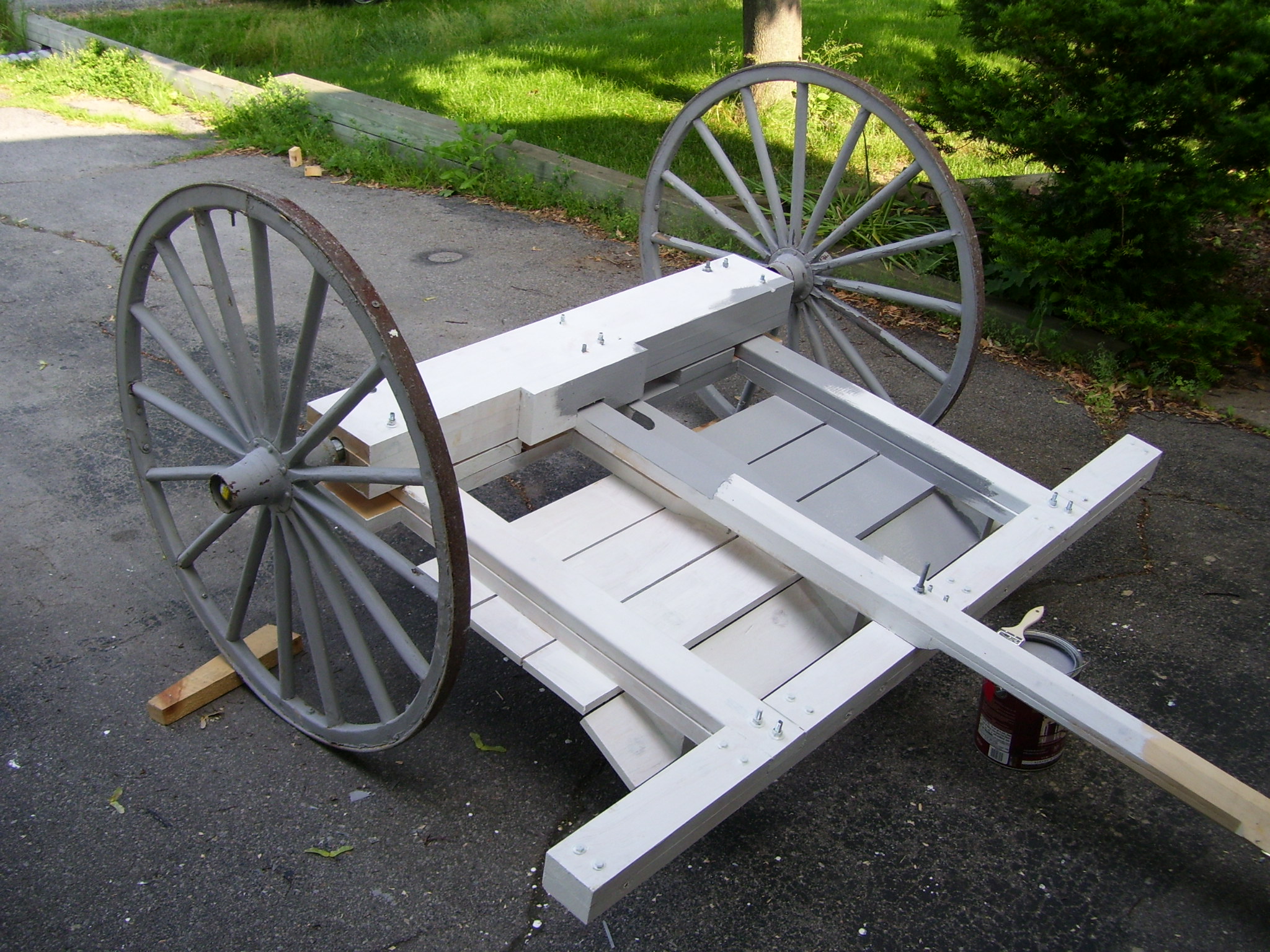
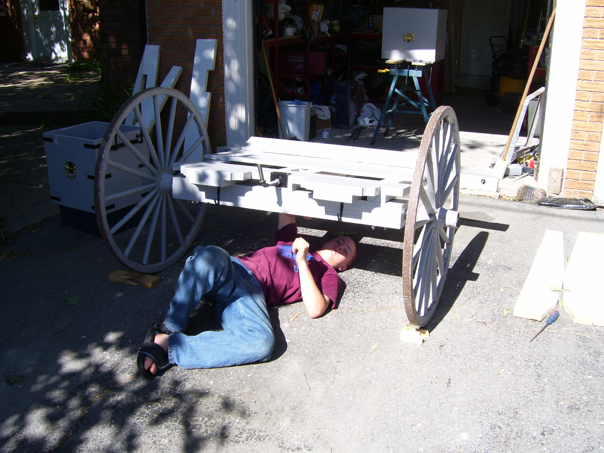
Step 1: The wheels
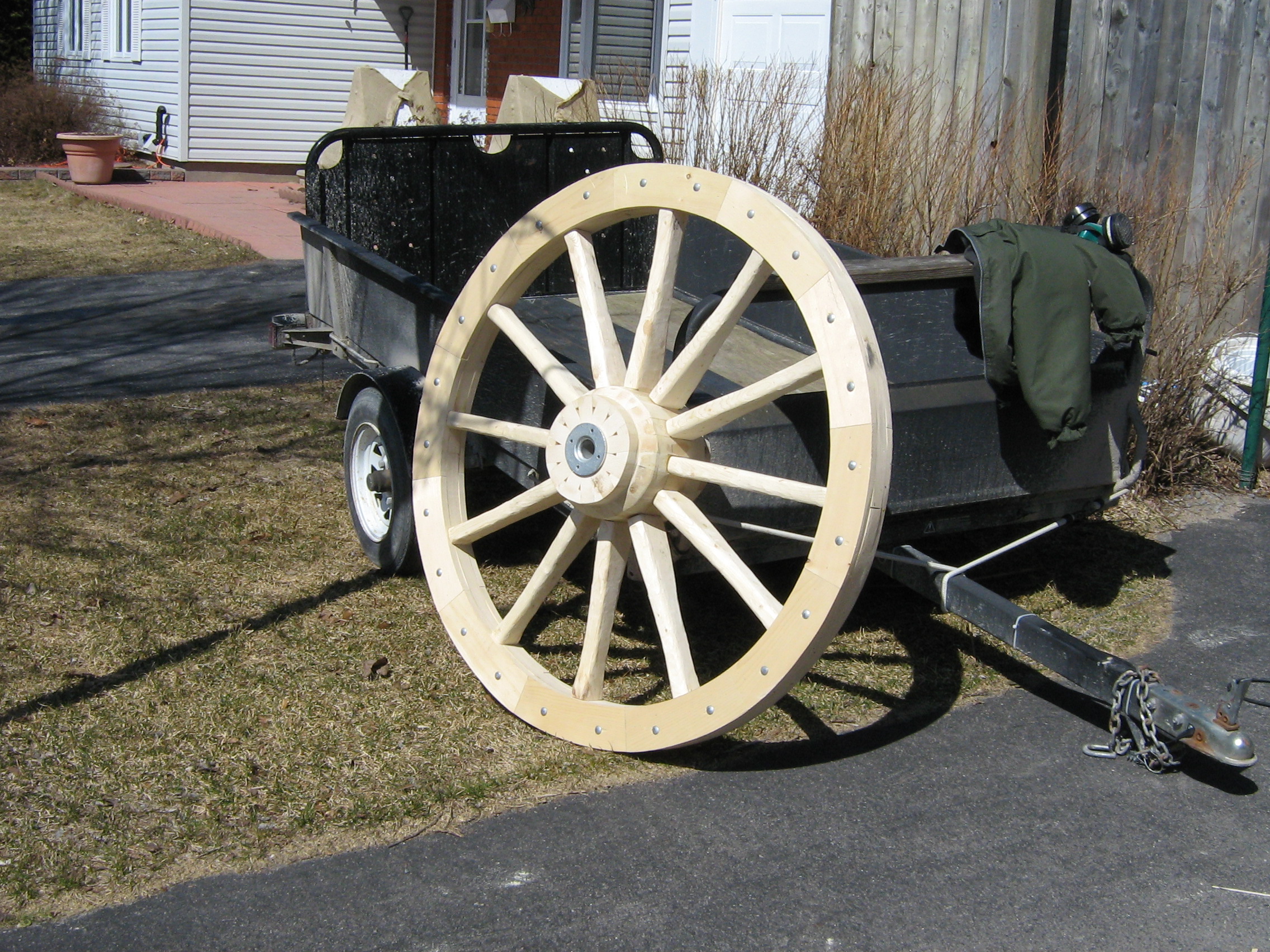
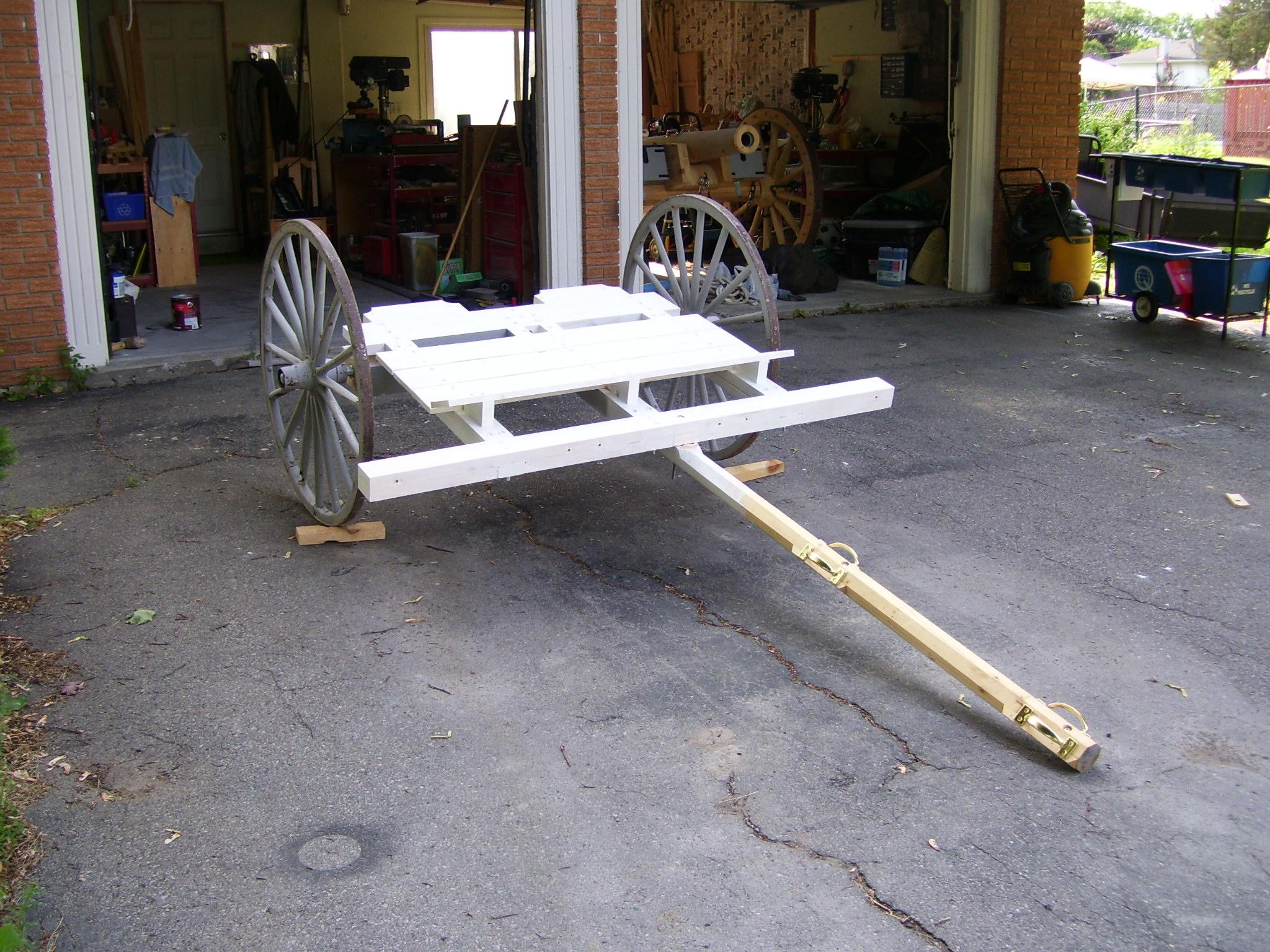
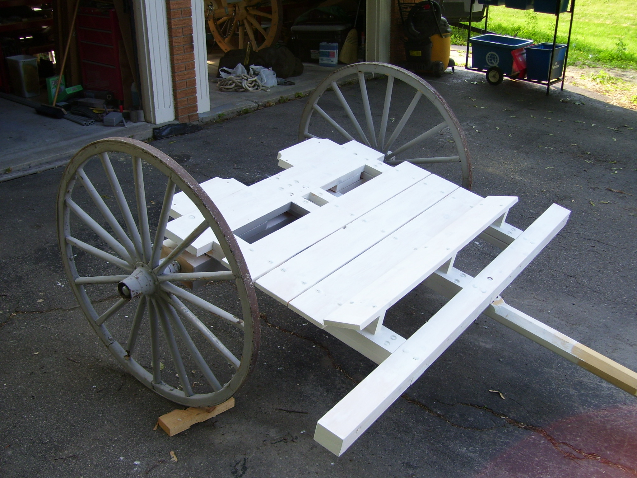
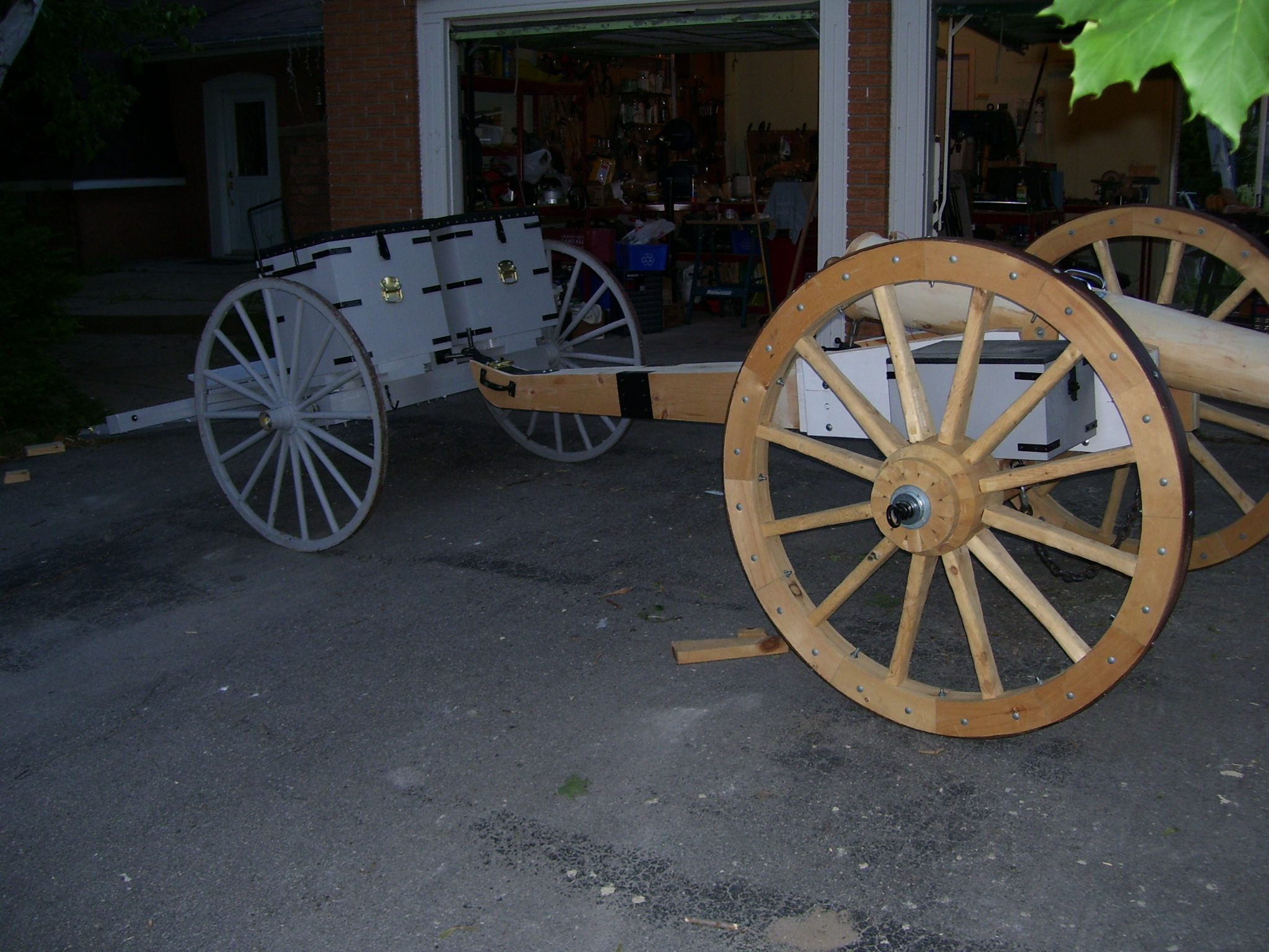
The limber wheels were originally a set of buggy wheels. However they proved to fragile for the task, and a second set of 4’ wheels were constructed. A detailed description of wheel construction is provided in the section for the Gun.
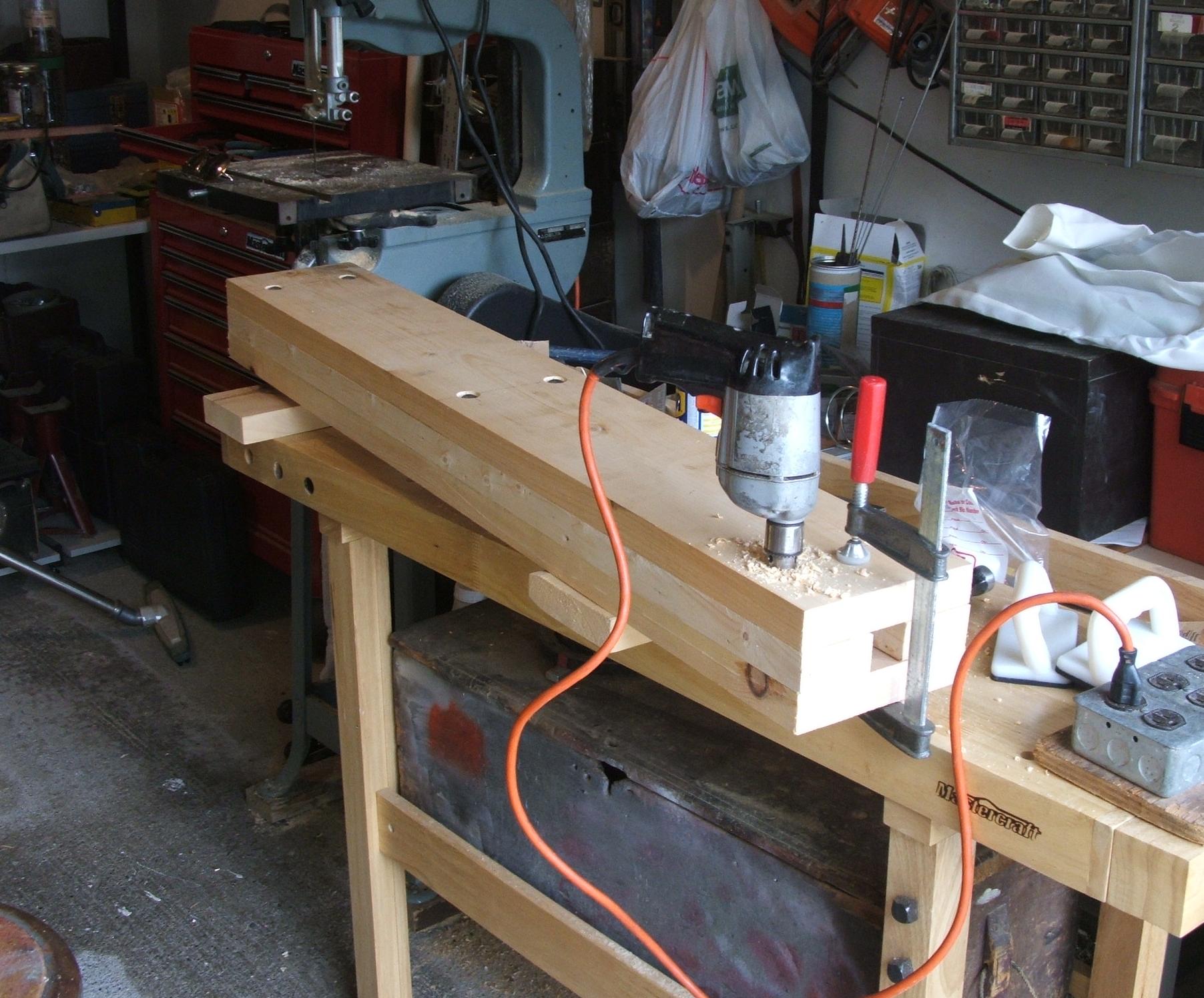
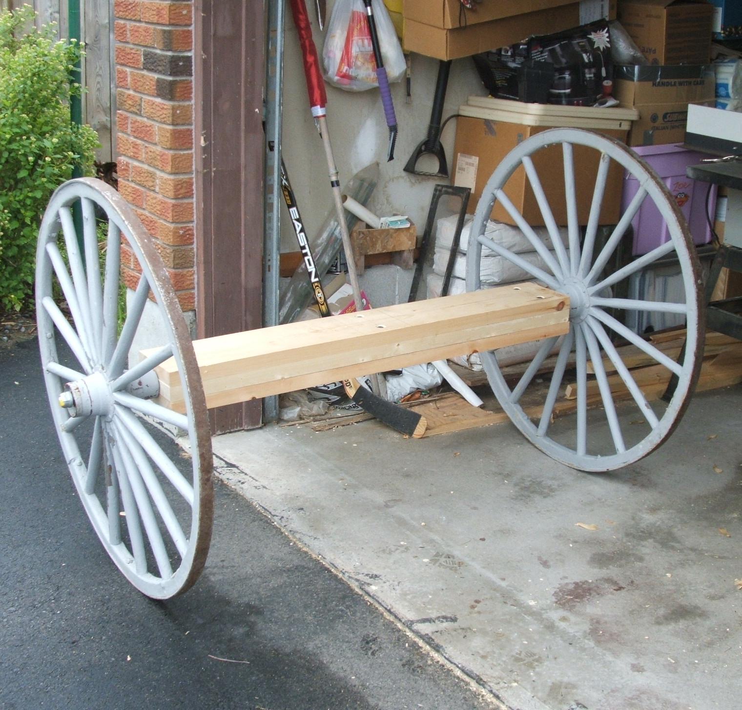
The Limber axletree is composed of 2x6 and 2x4 planks through which a 1” steel pipe axle is run. Each end of the axletree has a 1.25” flange and short-nipple bearing, to secure the axle and to keep it from wearing away the wood.
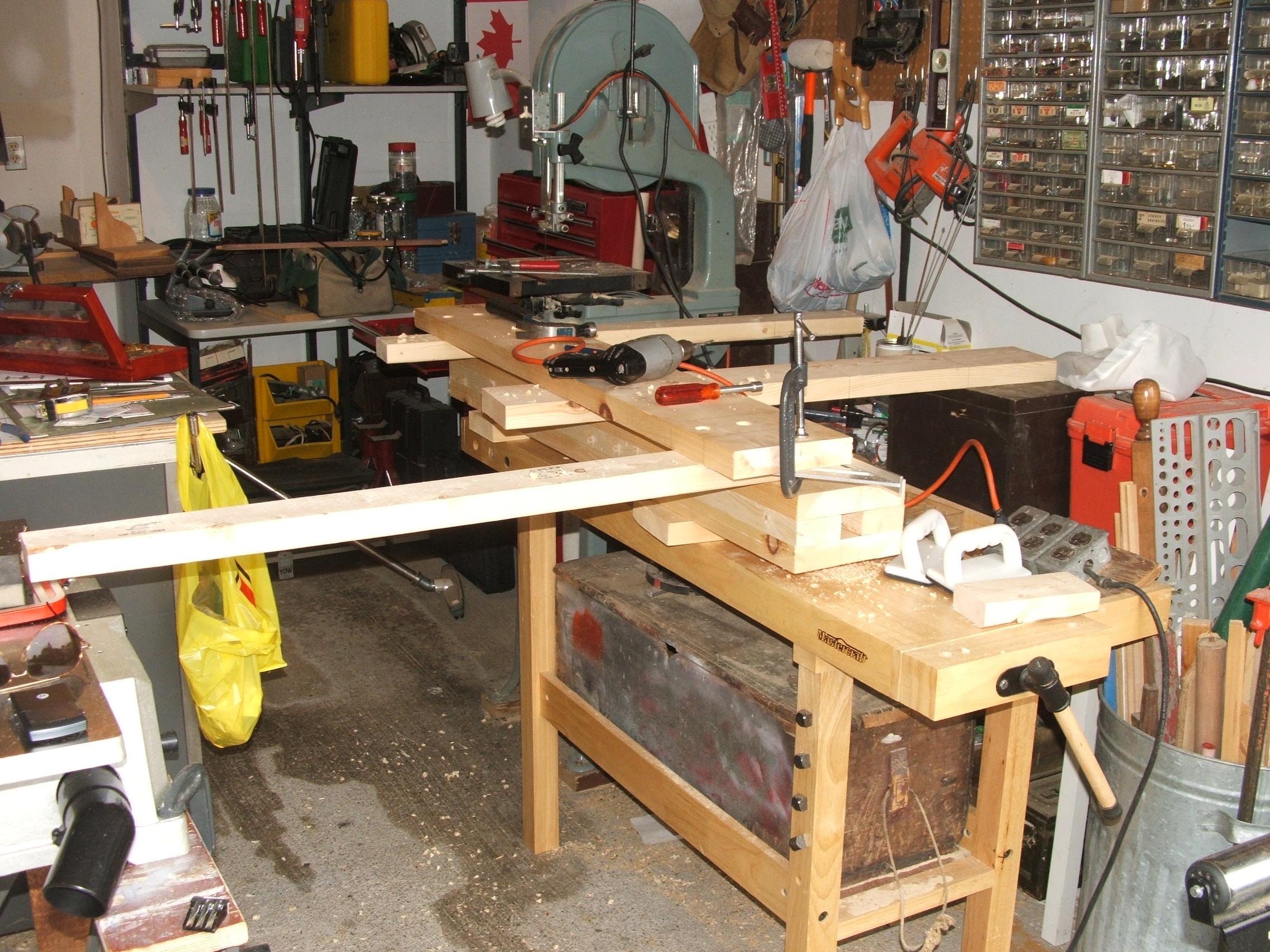
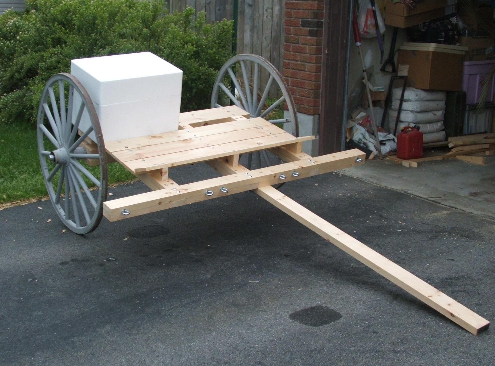
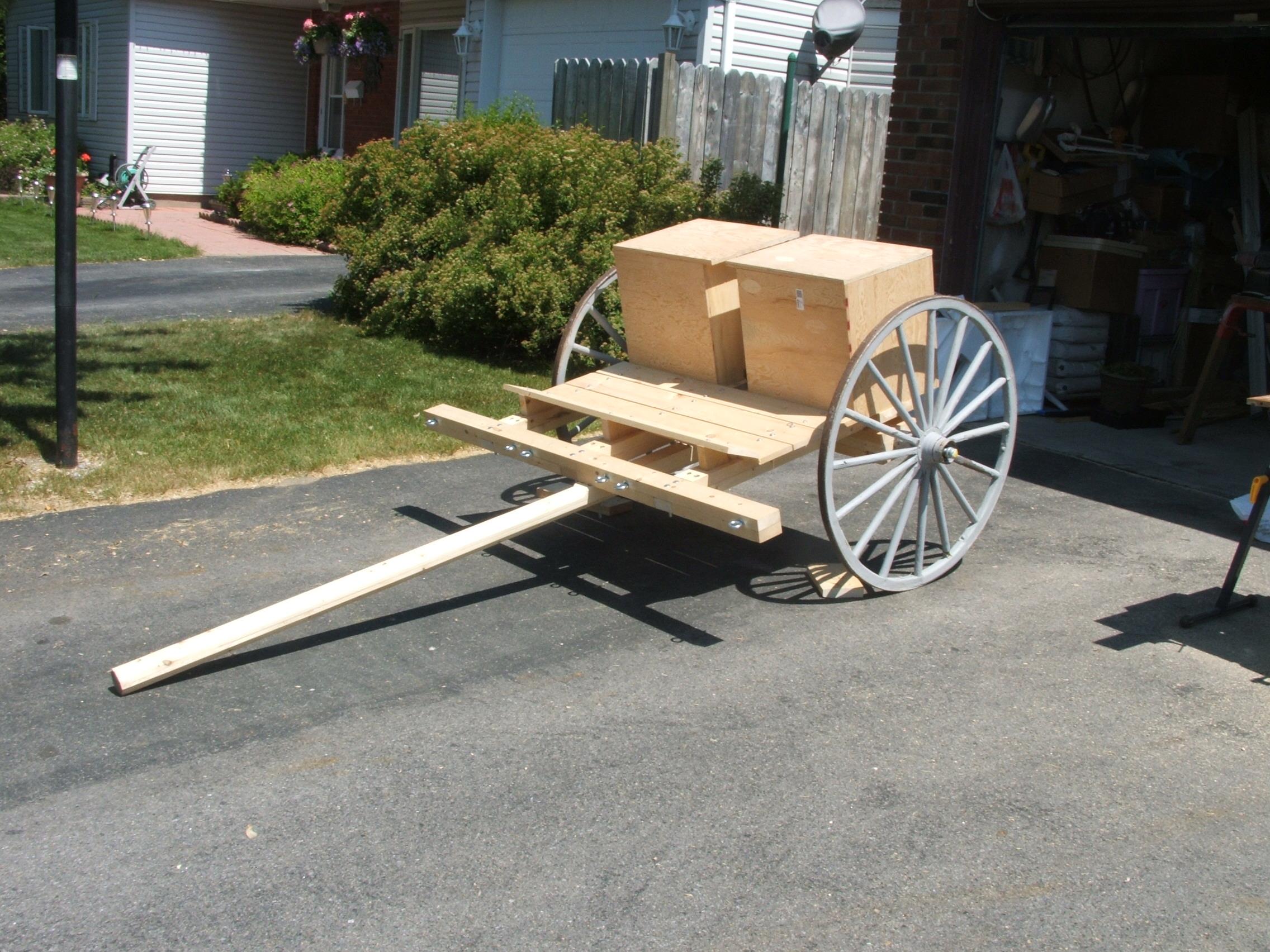
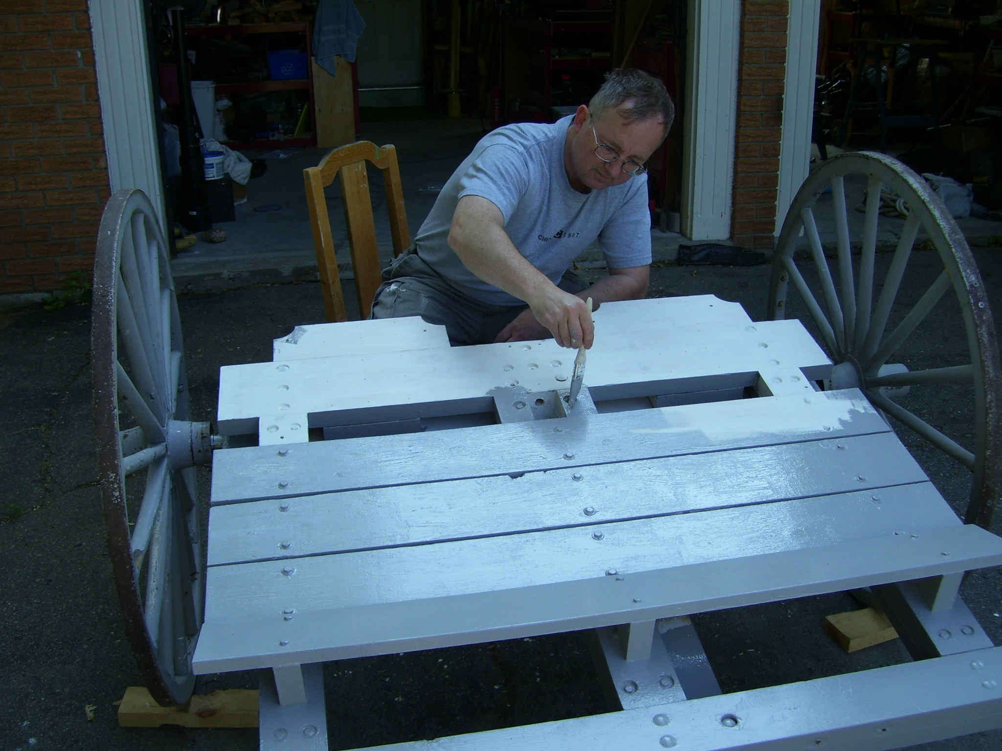
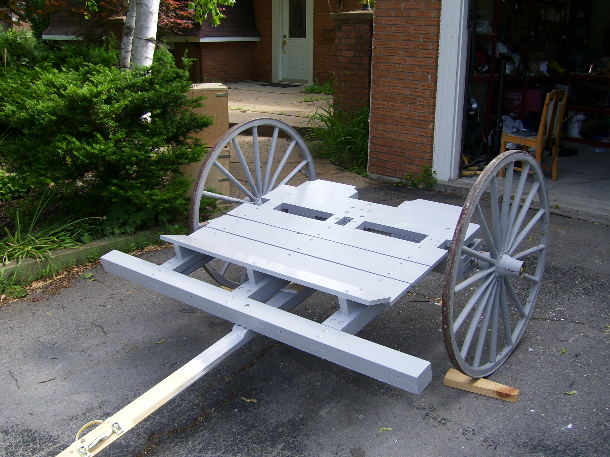
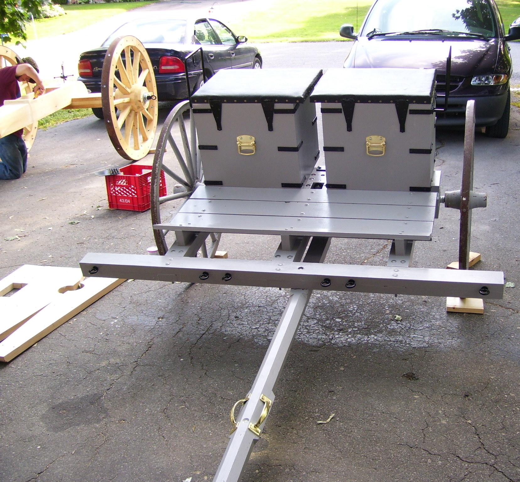
Step 2: Build the Limber Bed
The Limber axletree and bed were fabricated out of 1”x6”, 2”x4”, 2”x6” and 2”x8” select pine, again to keep the weight at a minimum.
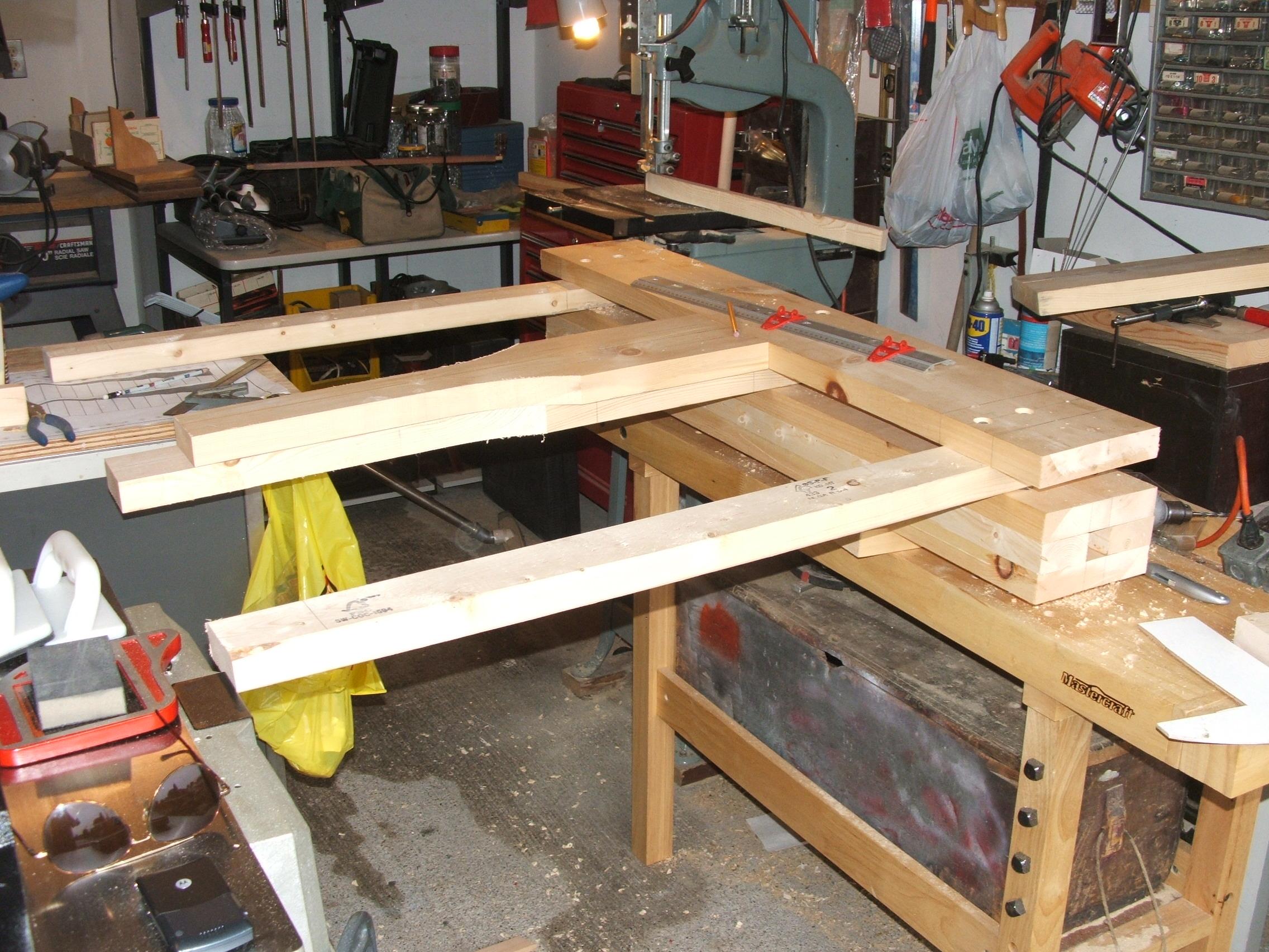
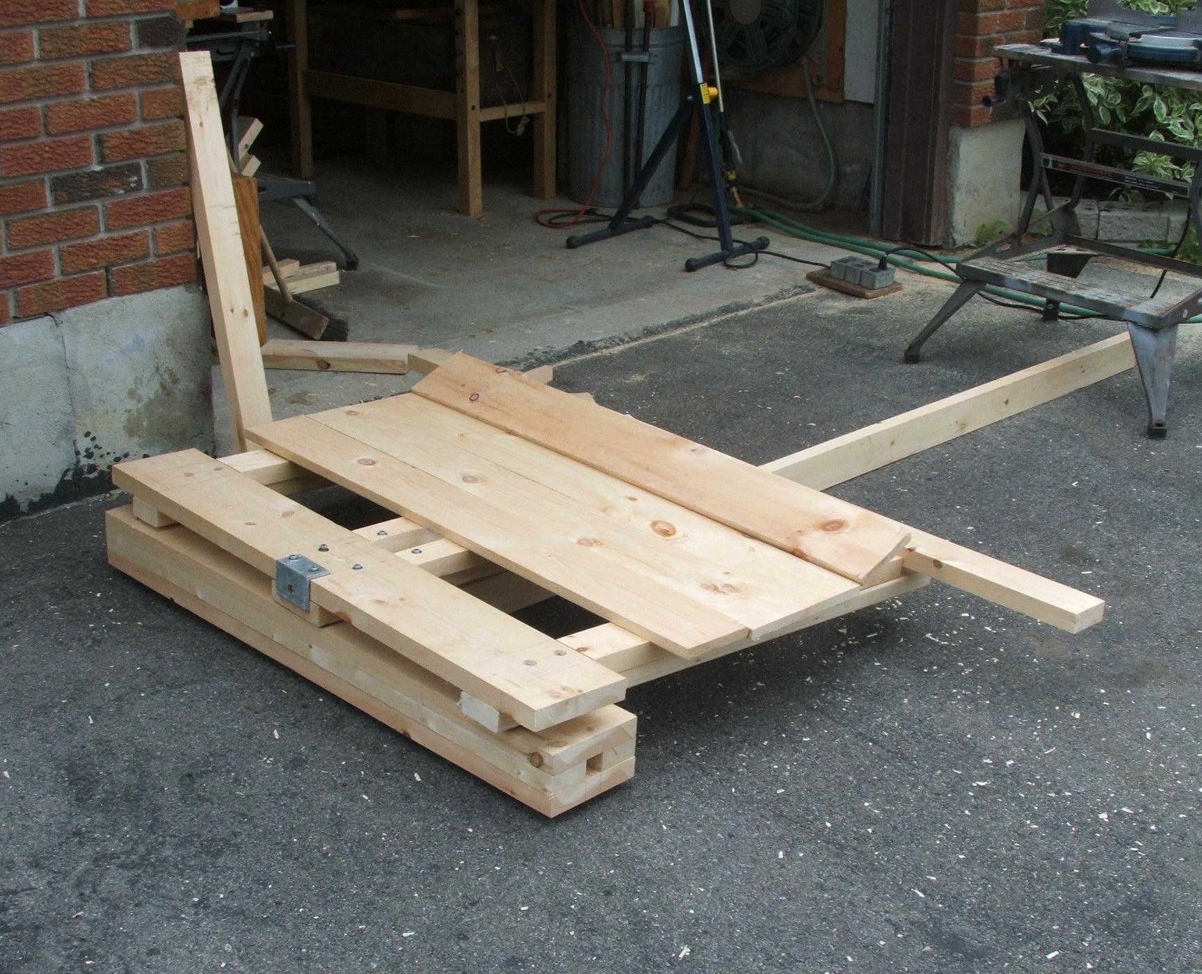
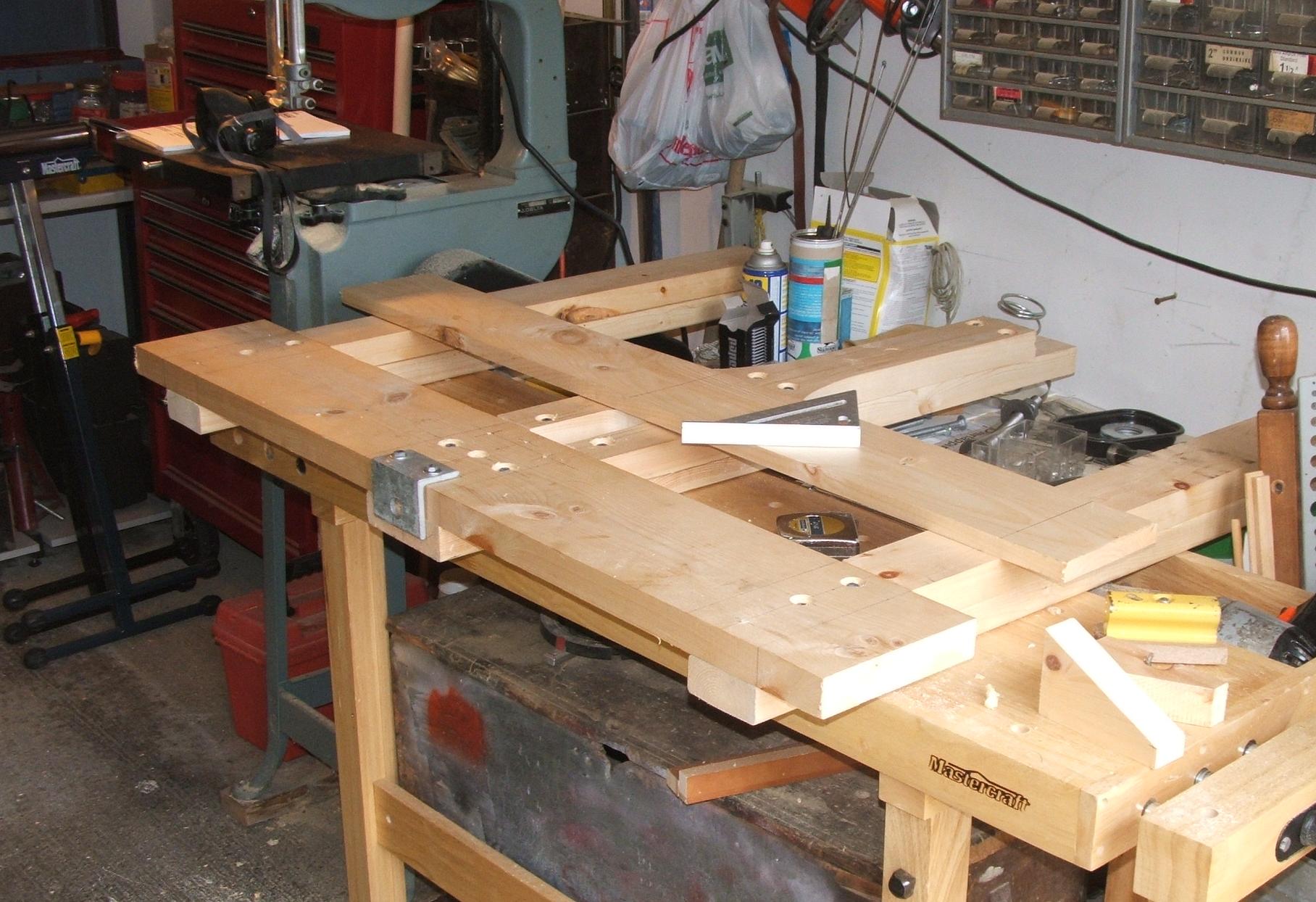
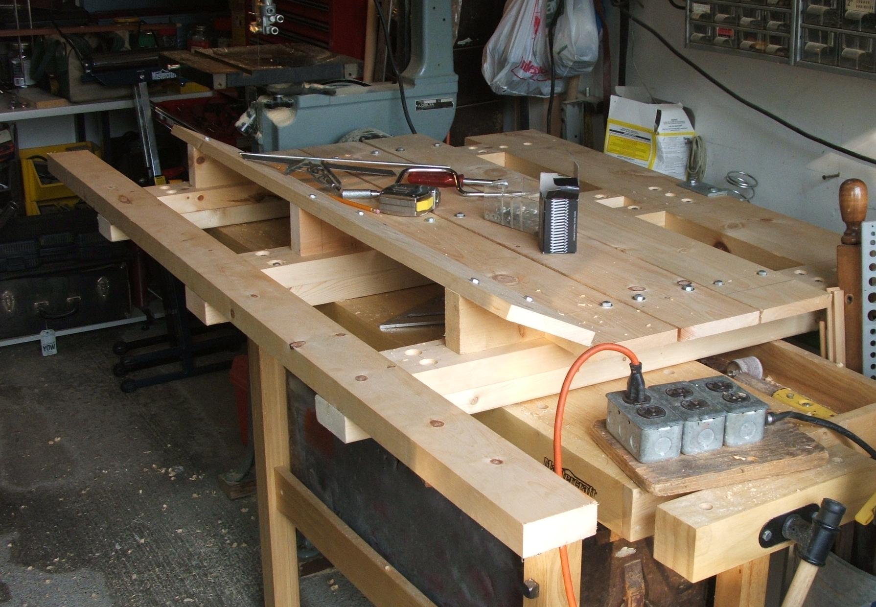
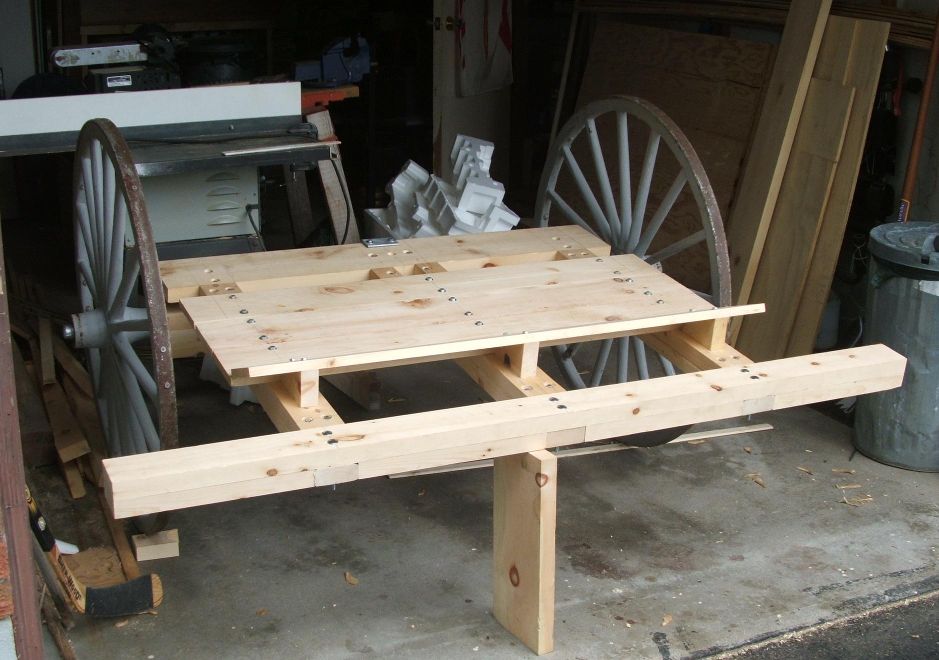
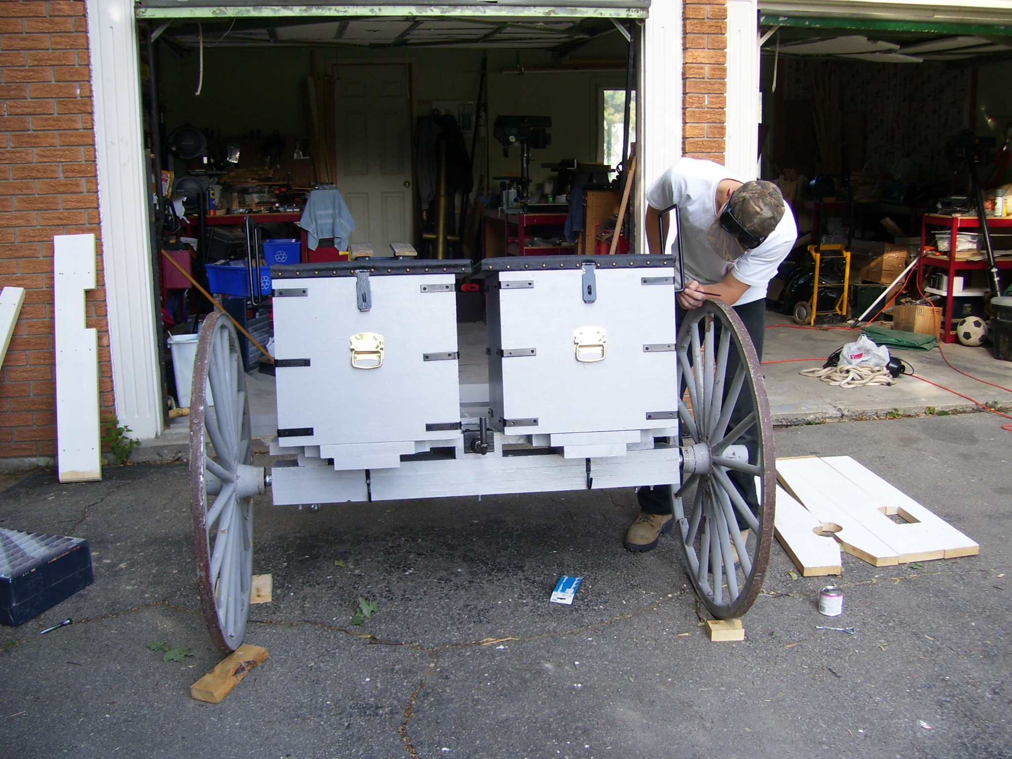
The rear of the limber is equipped with a ‘back porch’ to support each ammo box, and with a pulling hook for the cannon.
The splinter bar is equipped with eyebolts to facilitate a one or two horse pull. Hardware for the tongues is yet to be added. However, for scouting use, the limber has a centre pole for easy movement by the artillery crew. Two pull-poles were constructed, a short one for loading and transport, and a longer one with crossbars for field use.
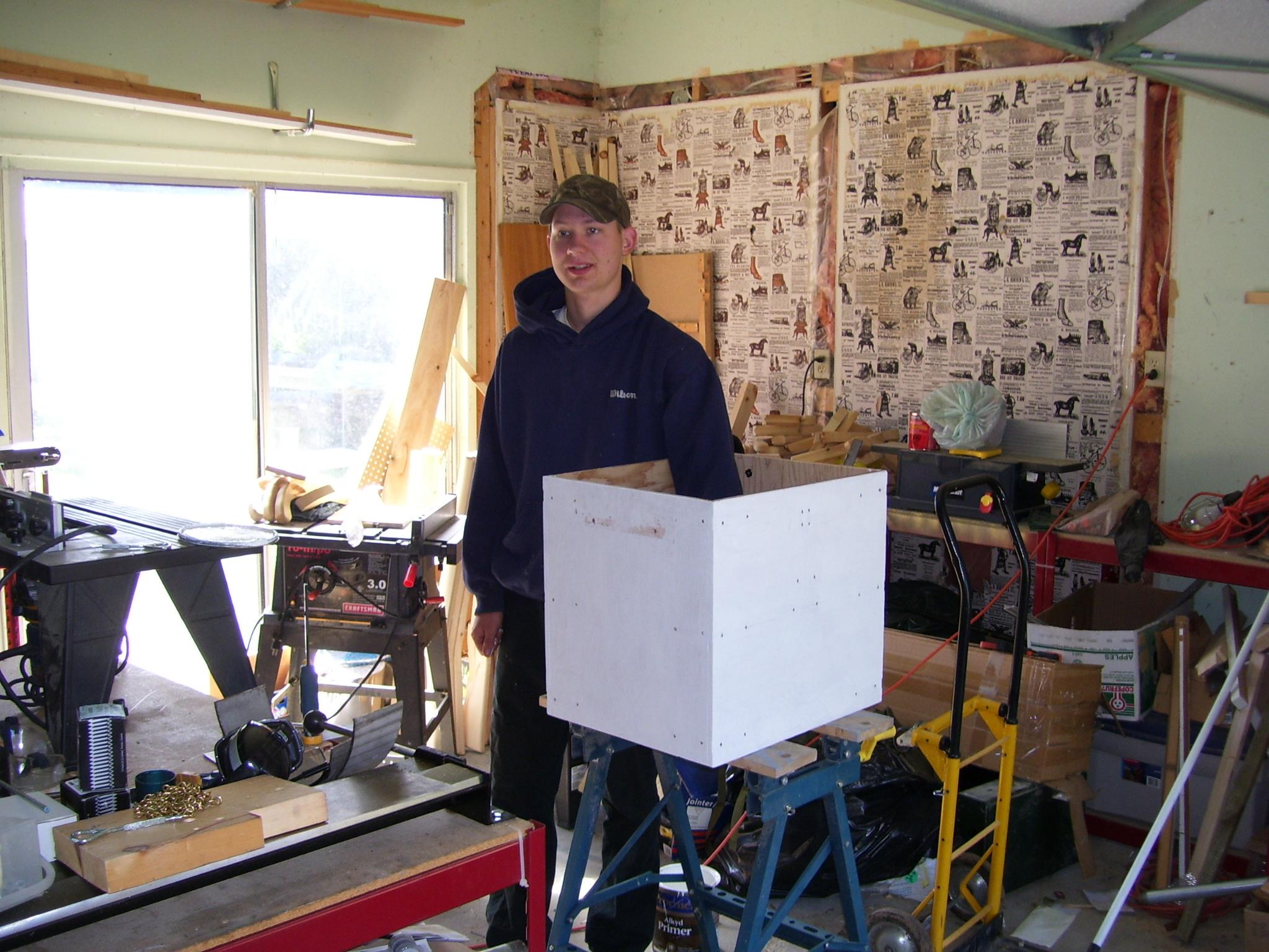
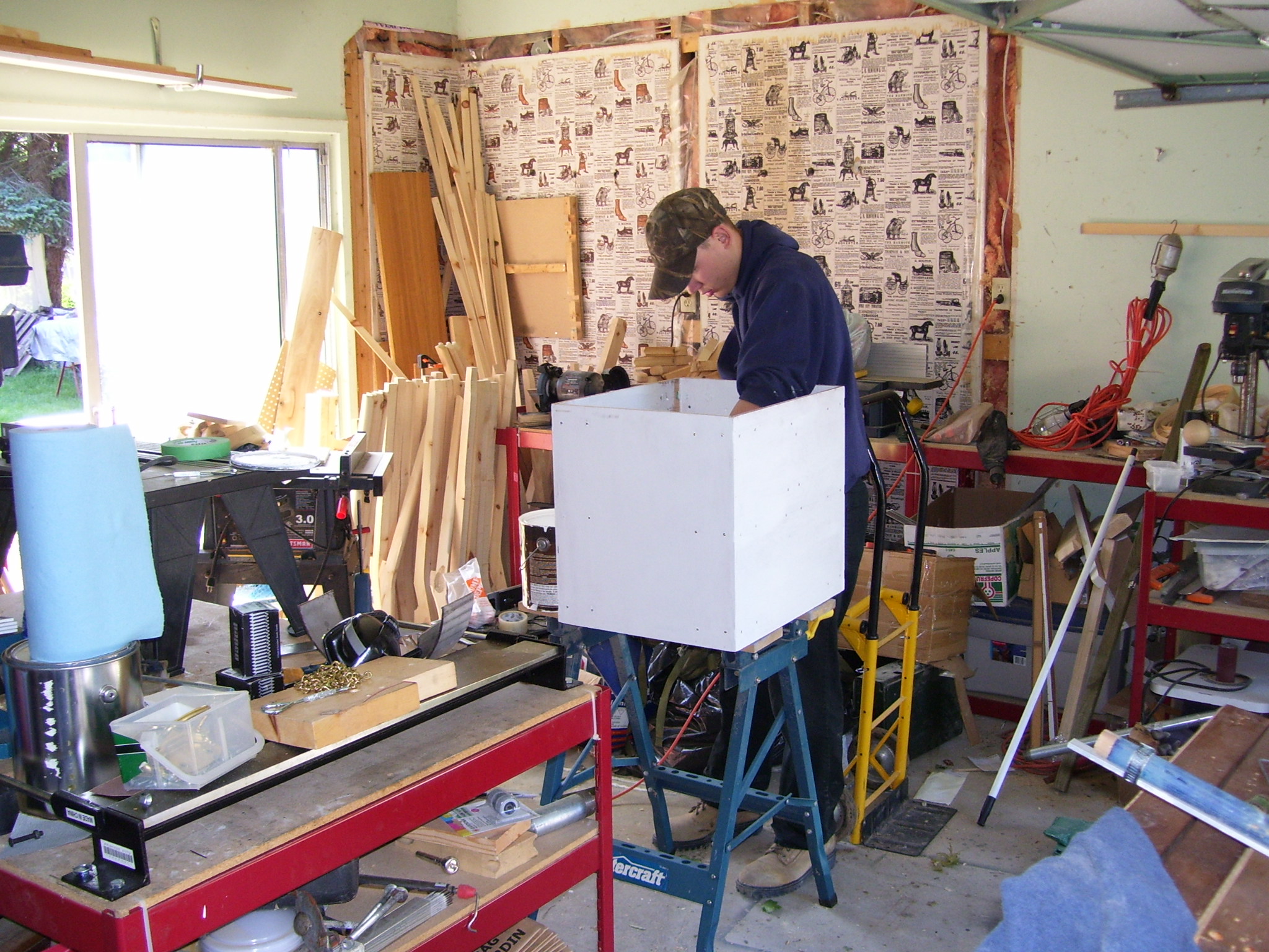
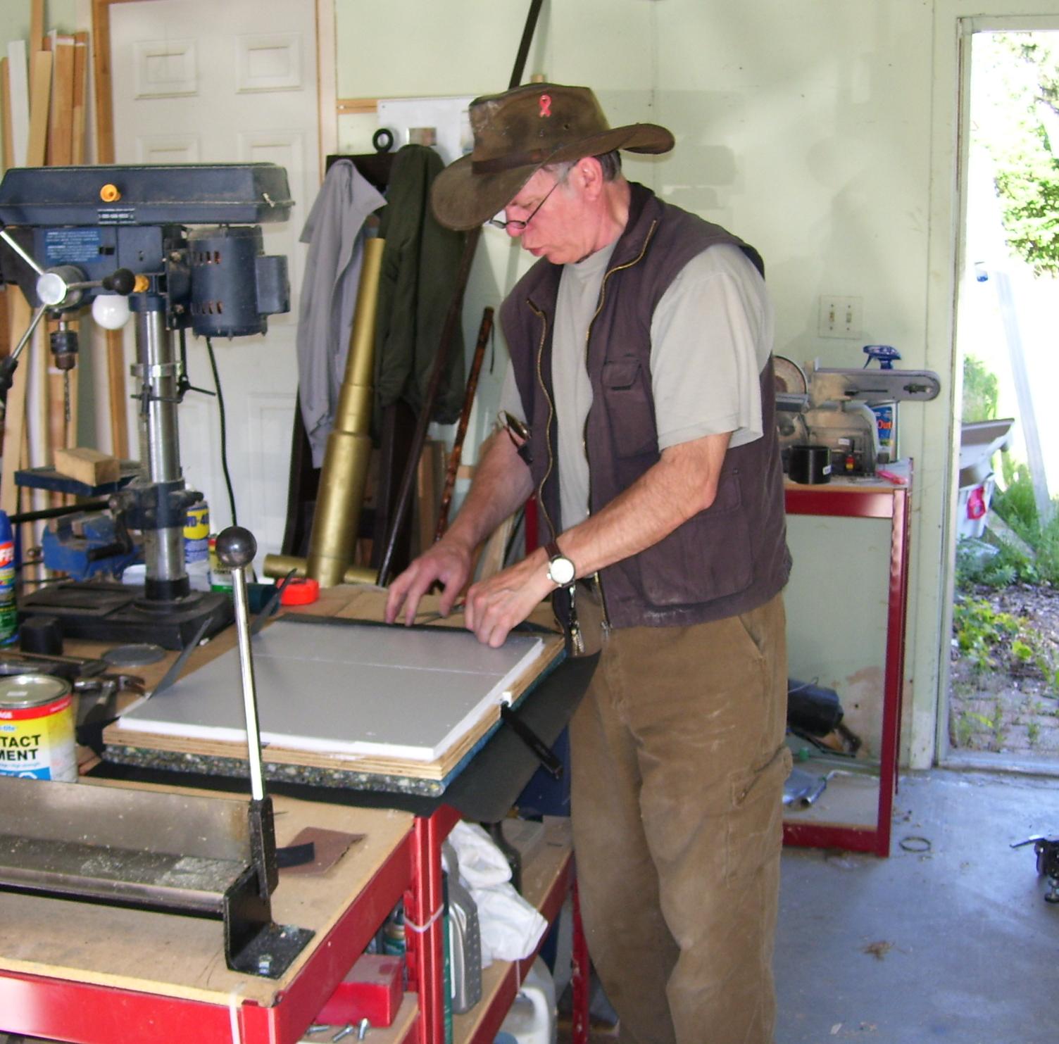
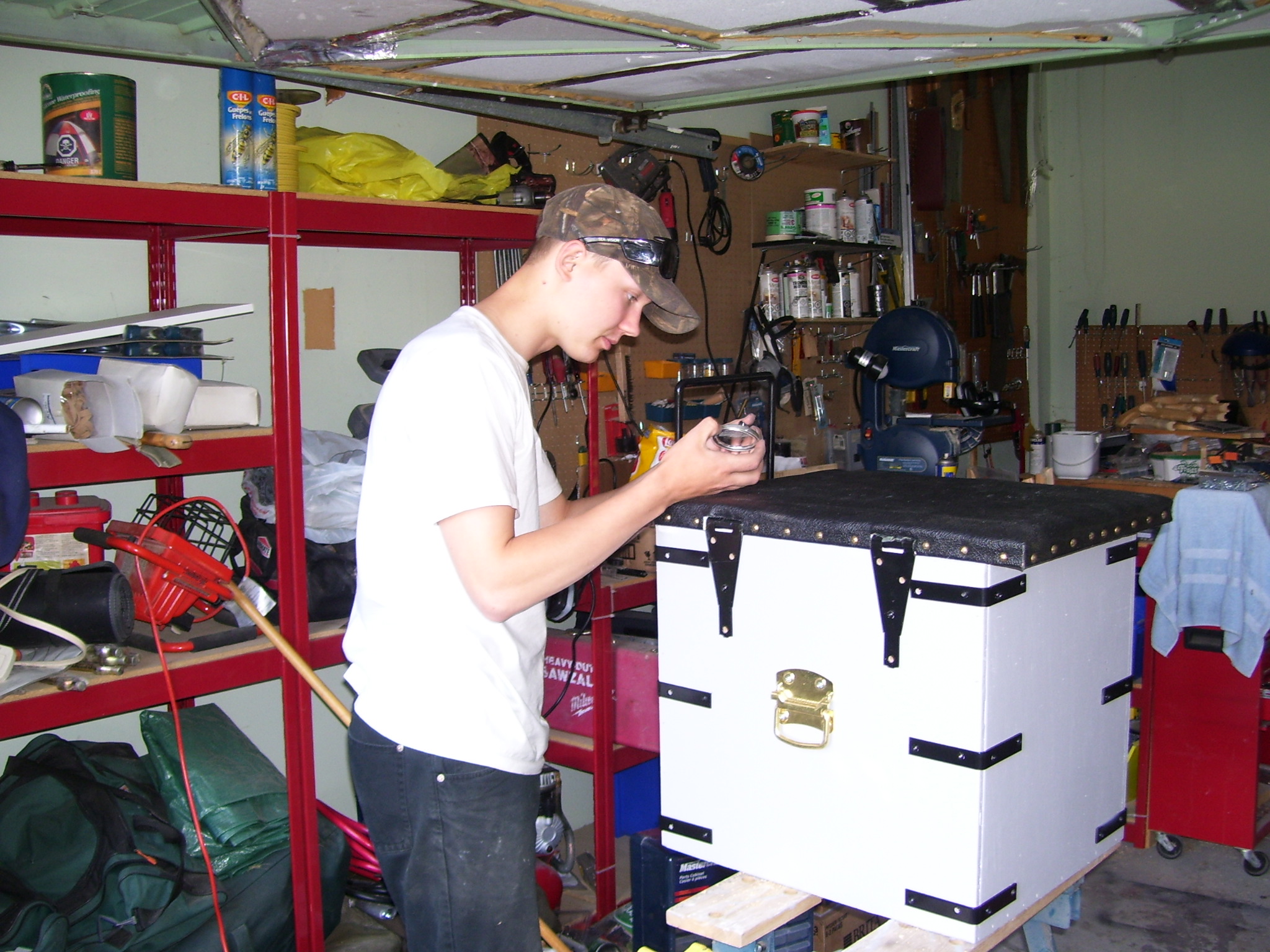
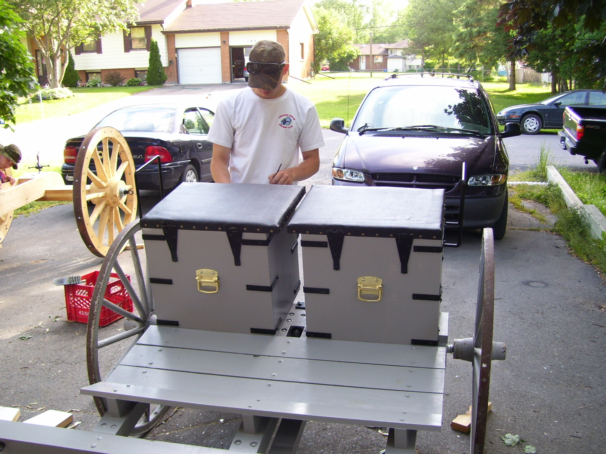
Step 3: Build the ammunition boxes
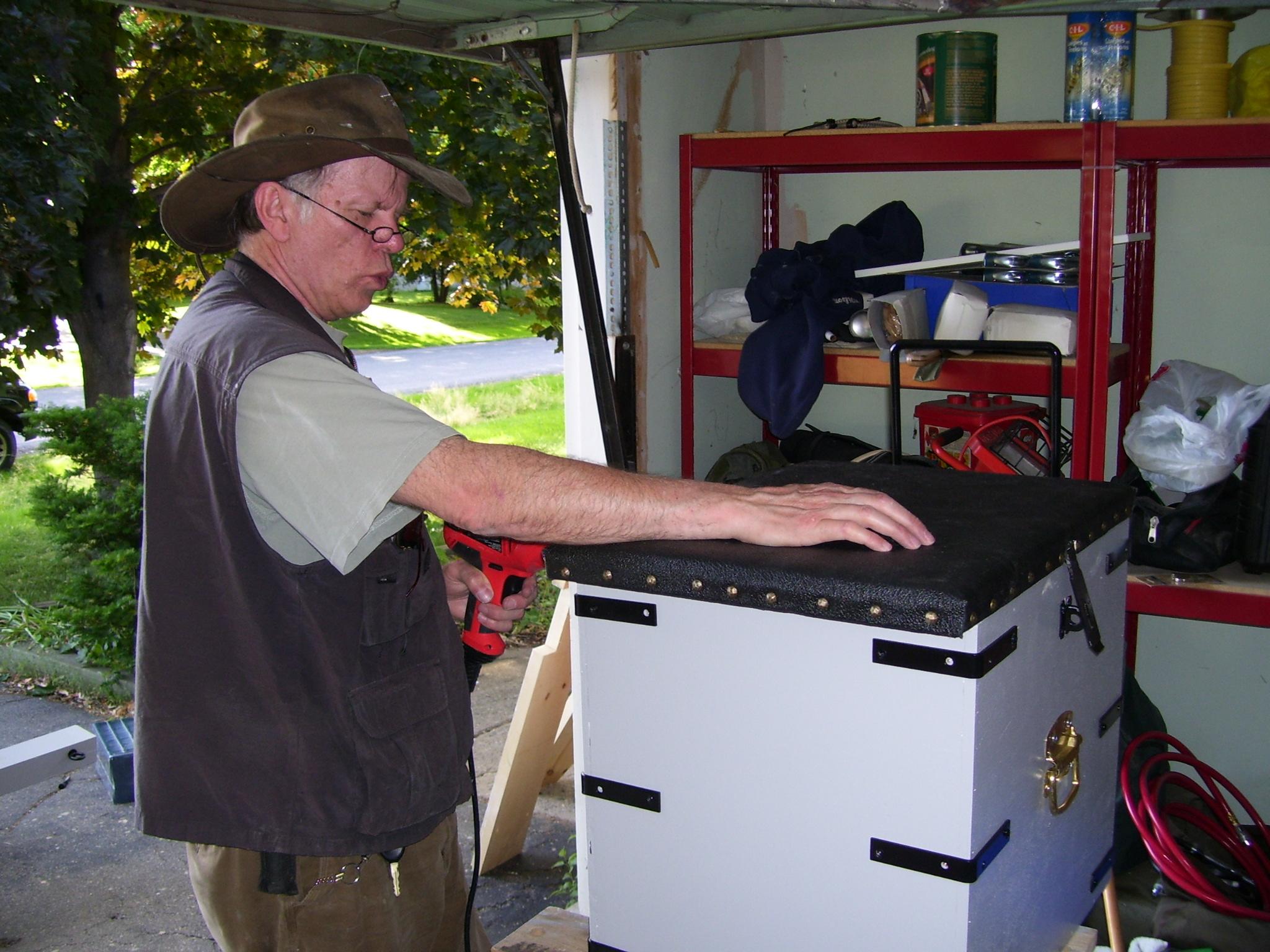
The ammo boxes are fabricated from ½” plywood, with provision for 16 x 4” cannon balls and accessories in each box. The completed box is reinforced with 16 L-brackets and is attached to the limber bed with wing-bolts and t-nuts.
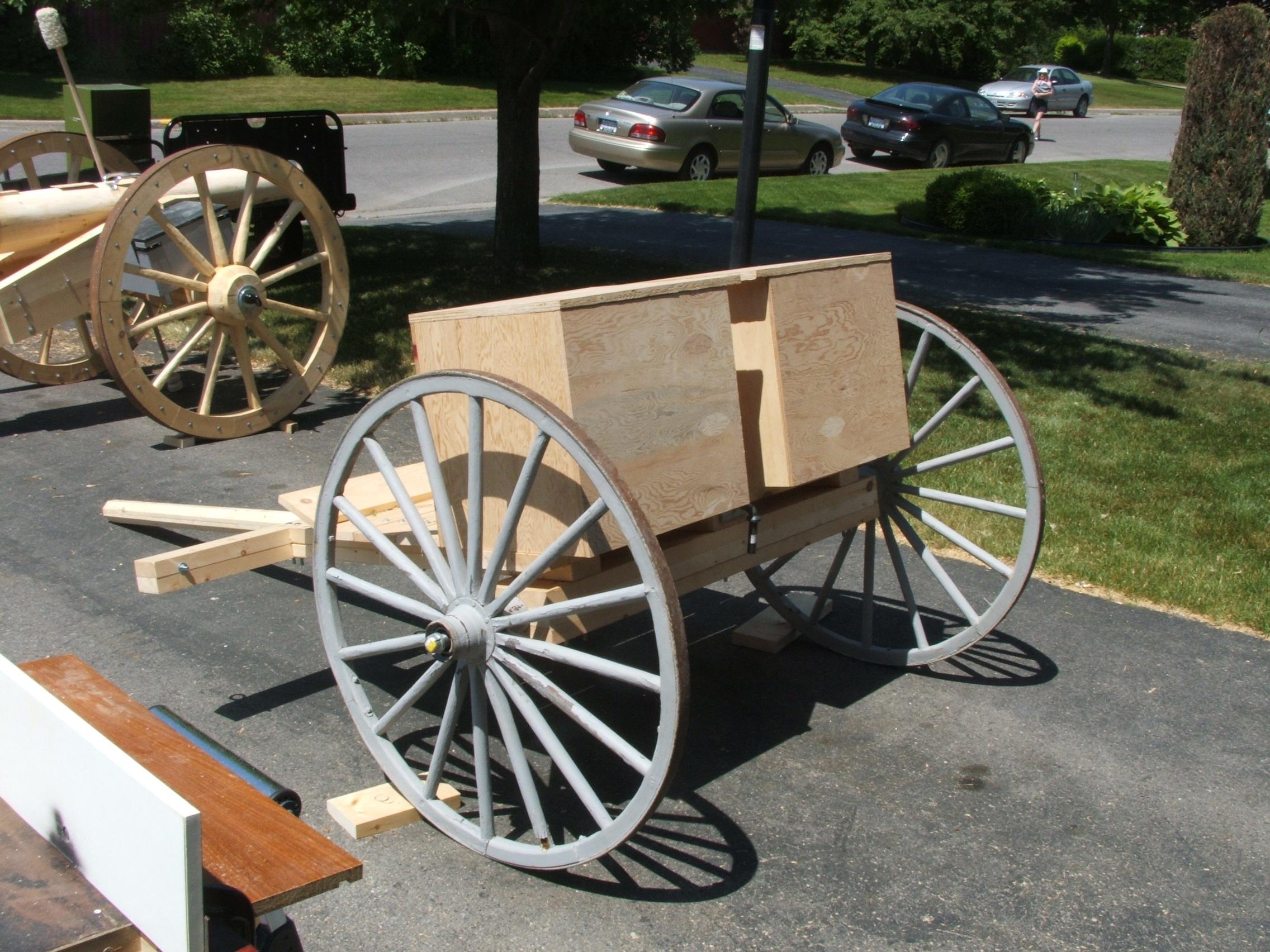
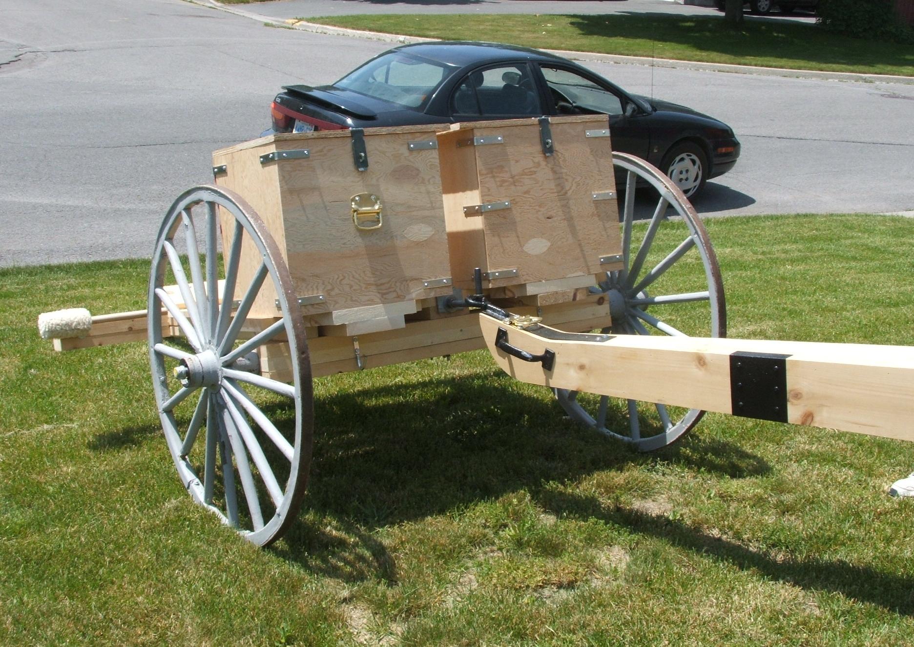
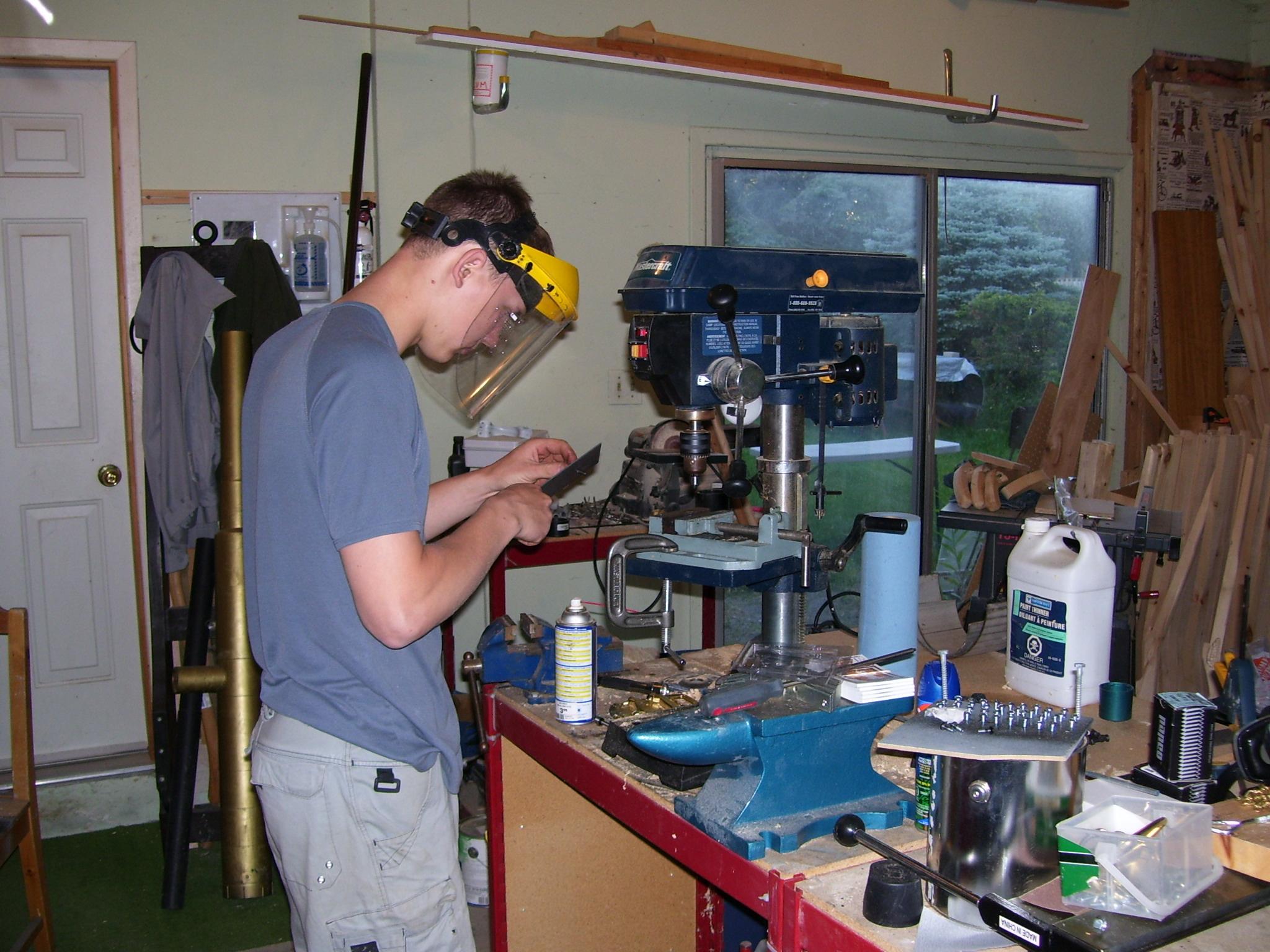
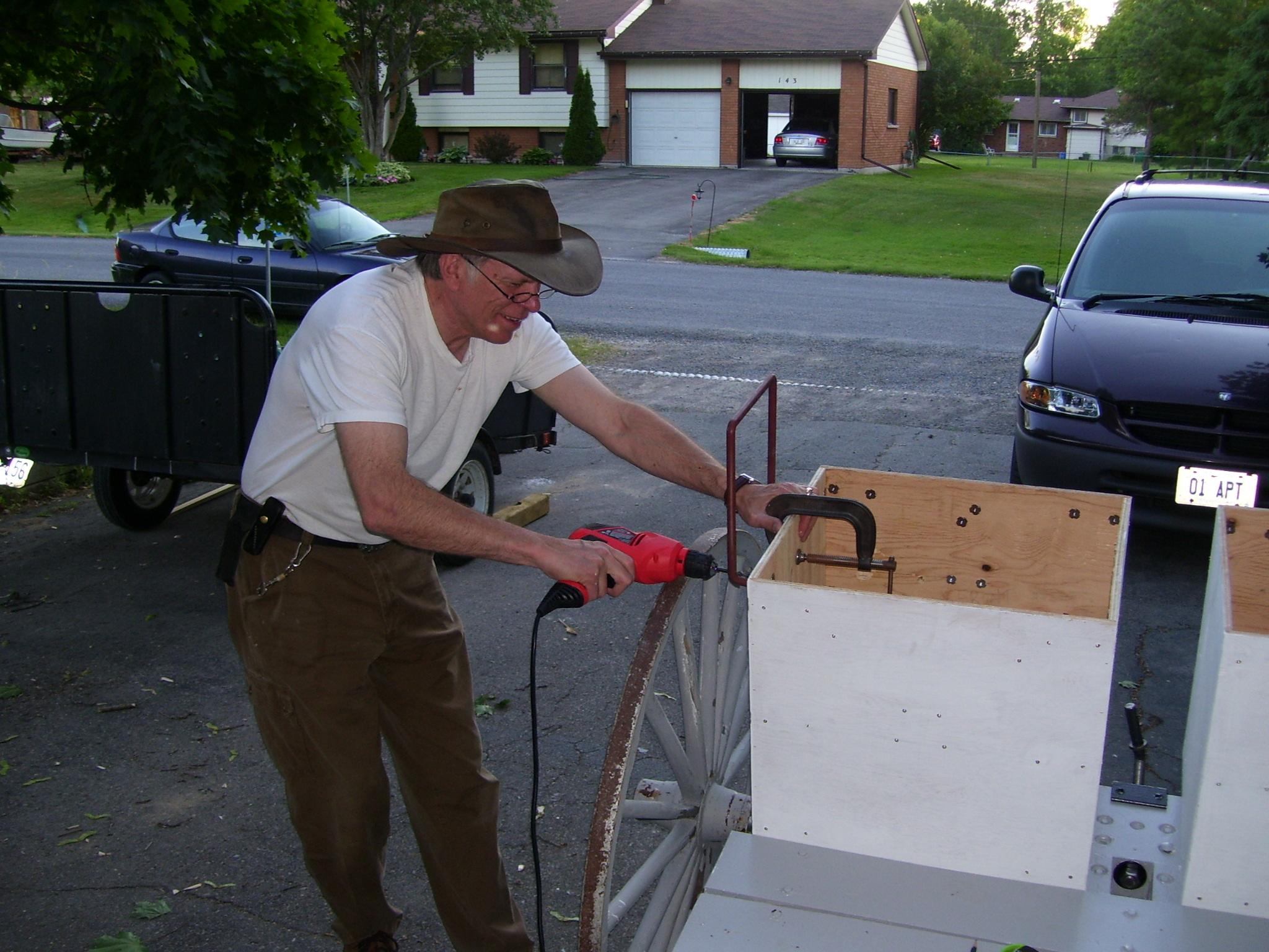
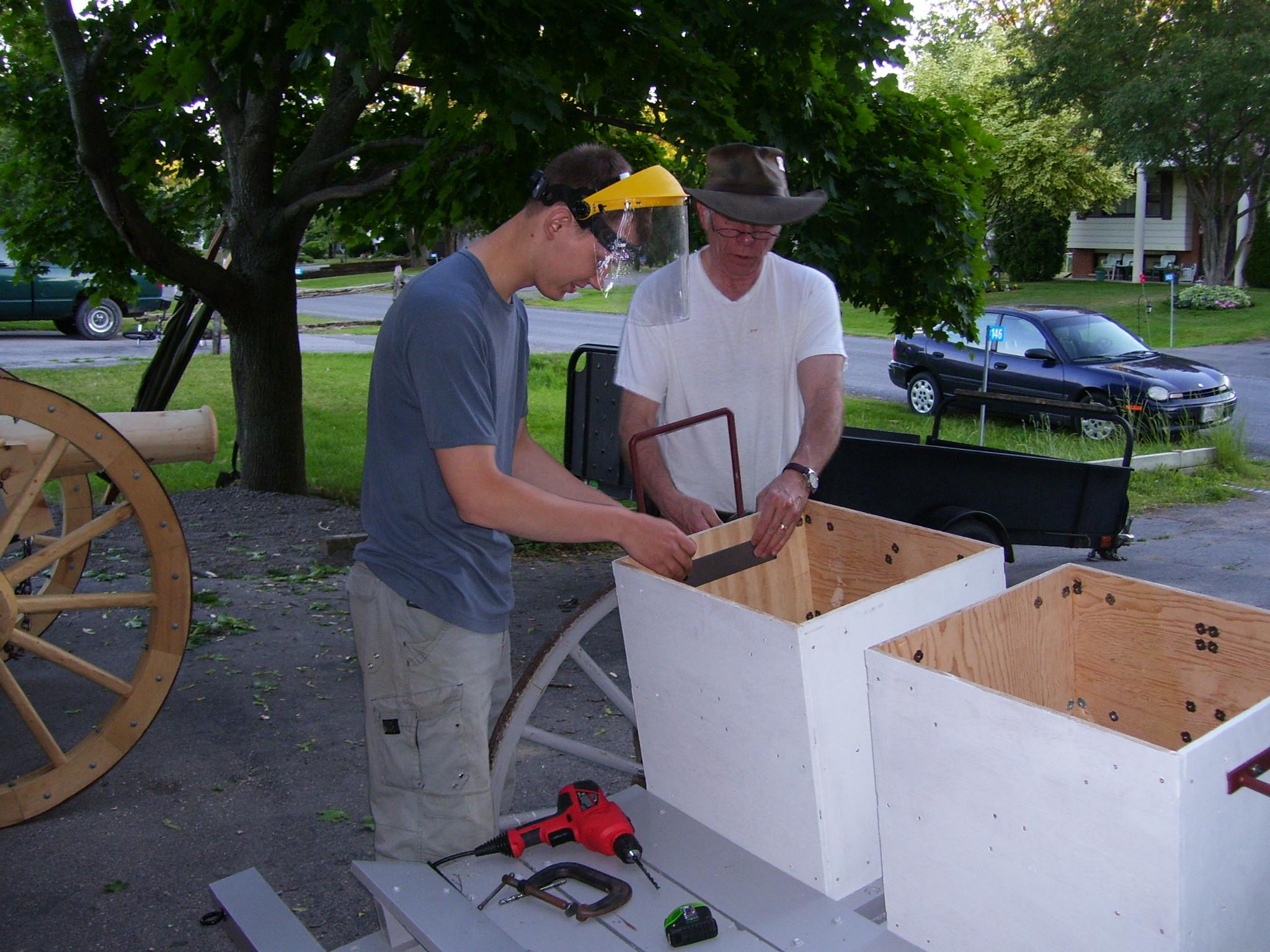
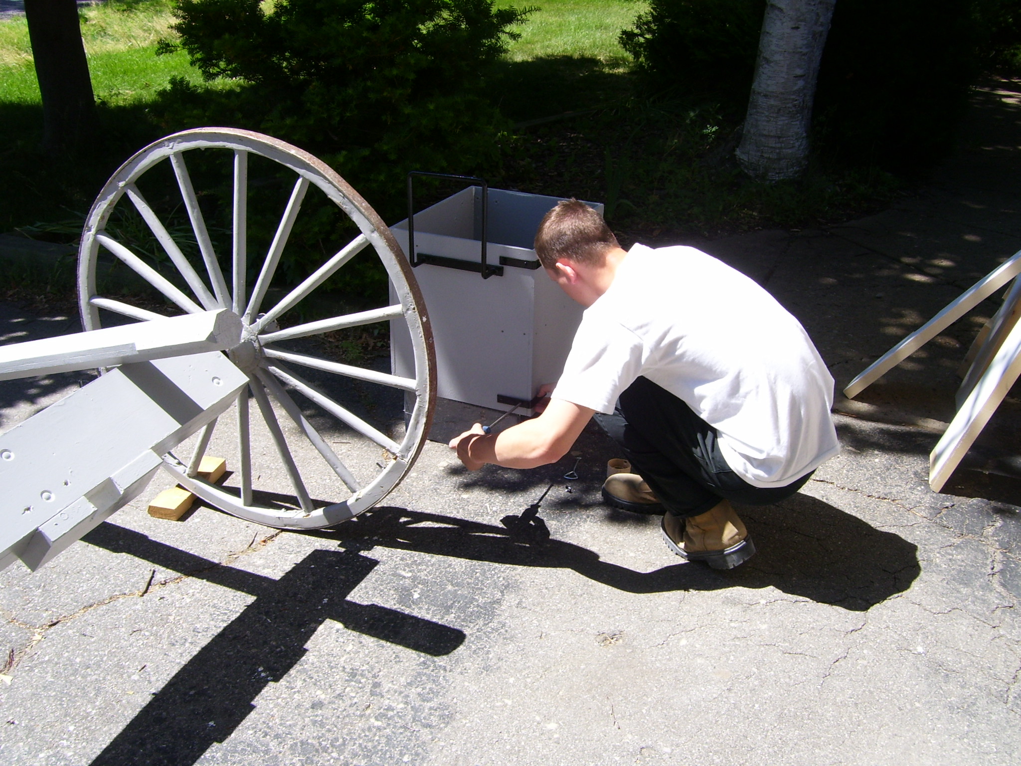
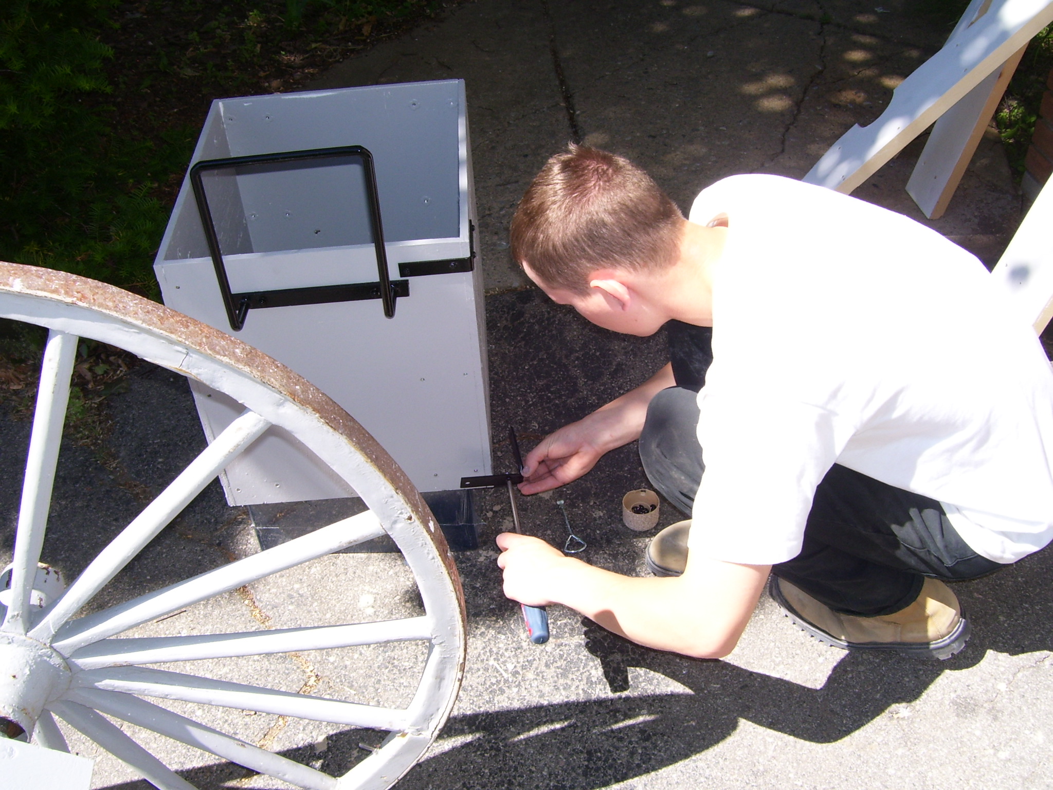
The box has a hinged lid, covered with a leatherette material, and equipped with a latch. The box is equipped with carrying handles and is bolted to the limber bed. In addition, a steel frame is attached to the side of each ammo box as a guard against slipping onto the wheel.
The livery is artillery grey with black hardware.
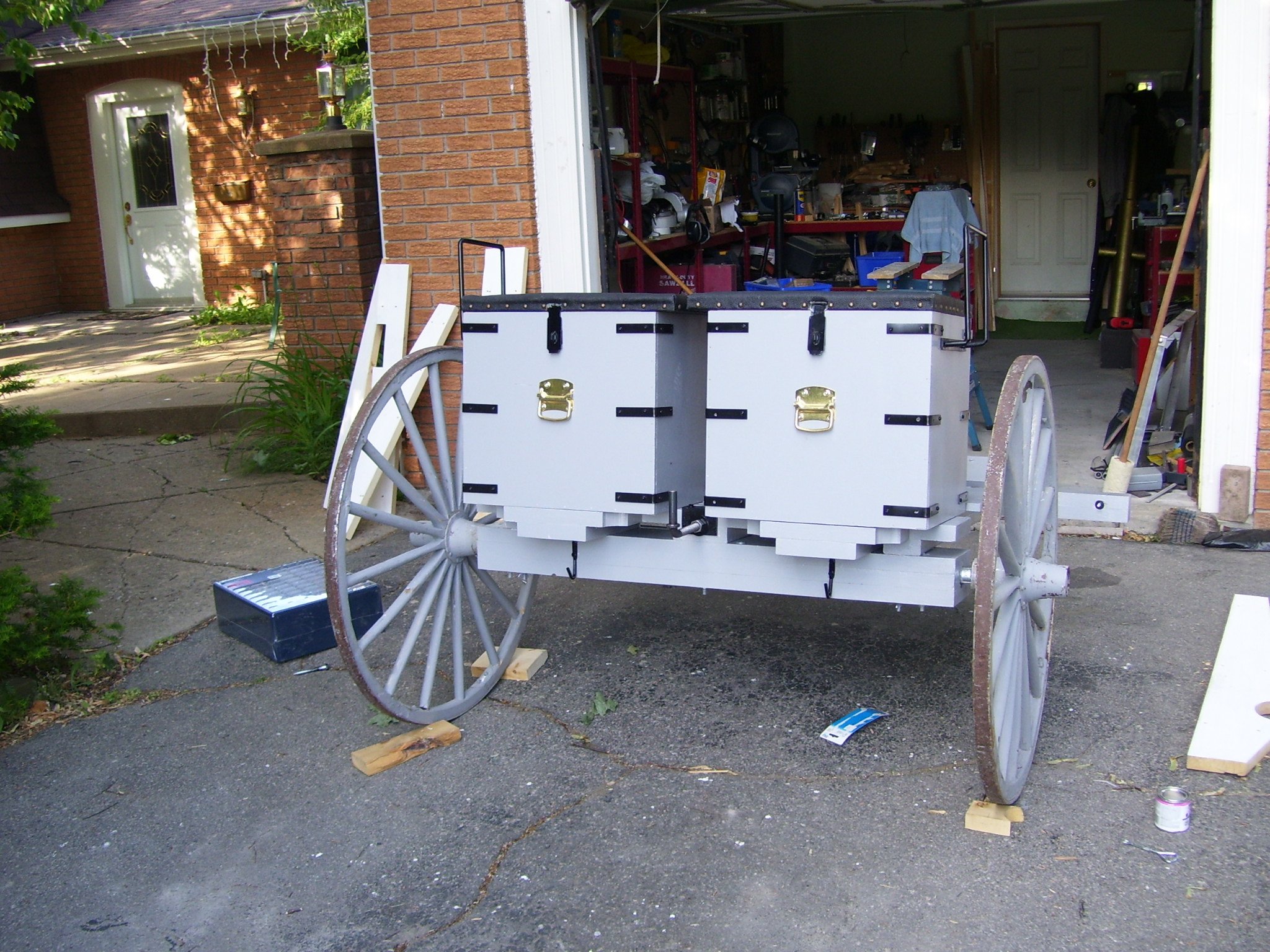
Step 4: Build the ammunition box covers
The lid is constructed of ¾” plywood and covered with padding and a leatherette material, as the lids also serve as seats for a driver and passenger.
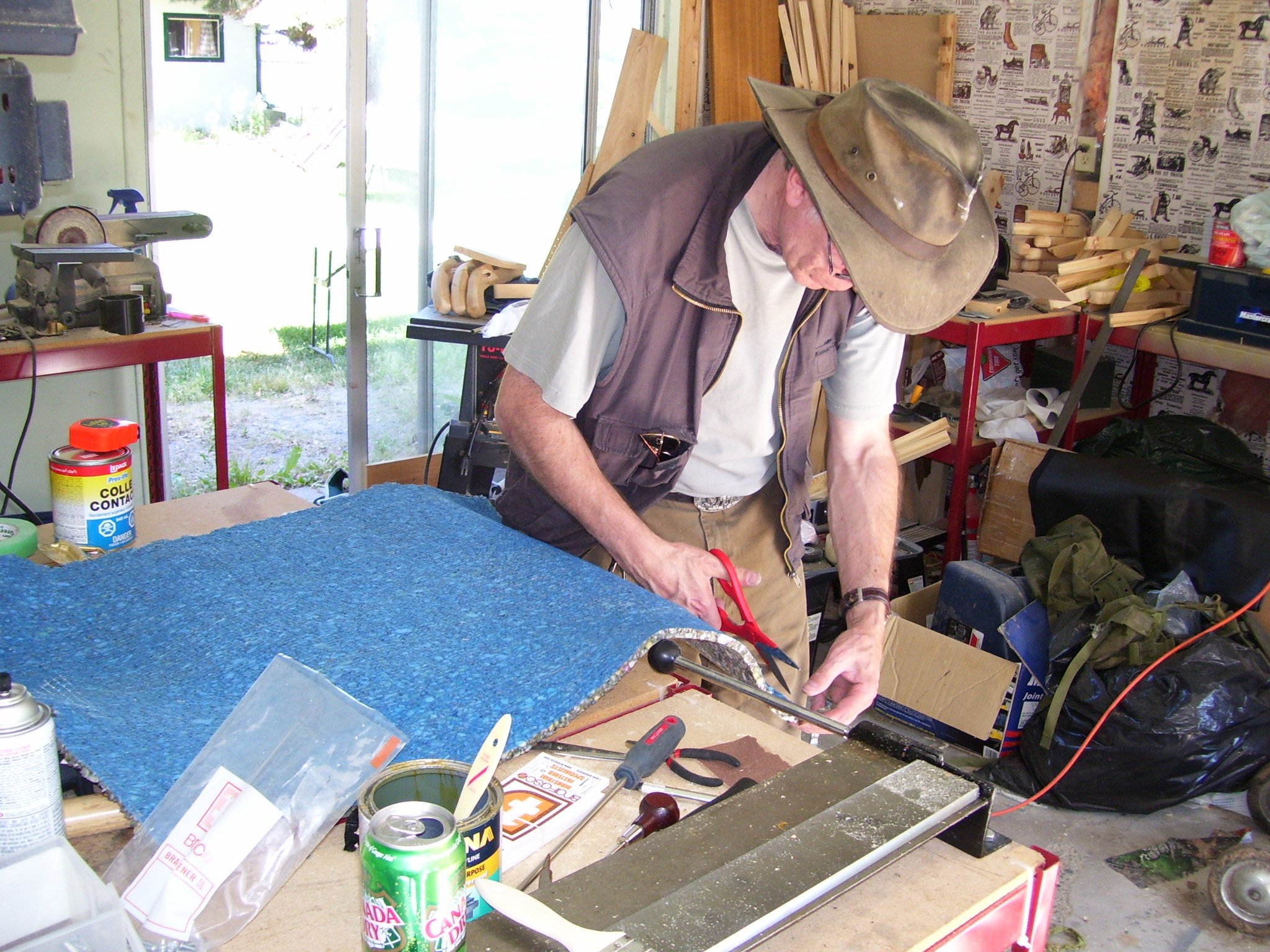
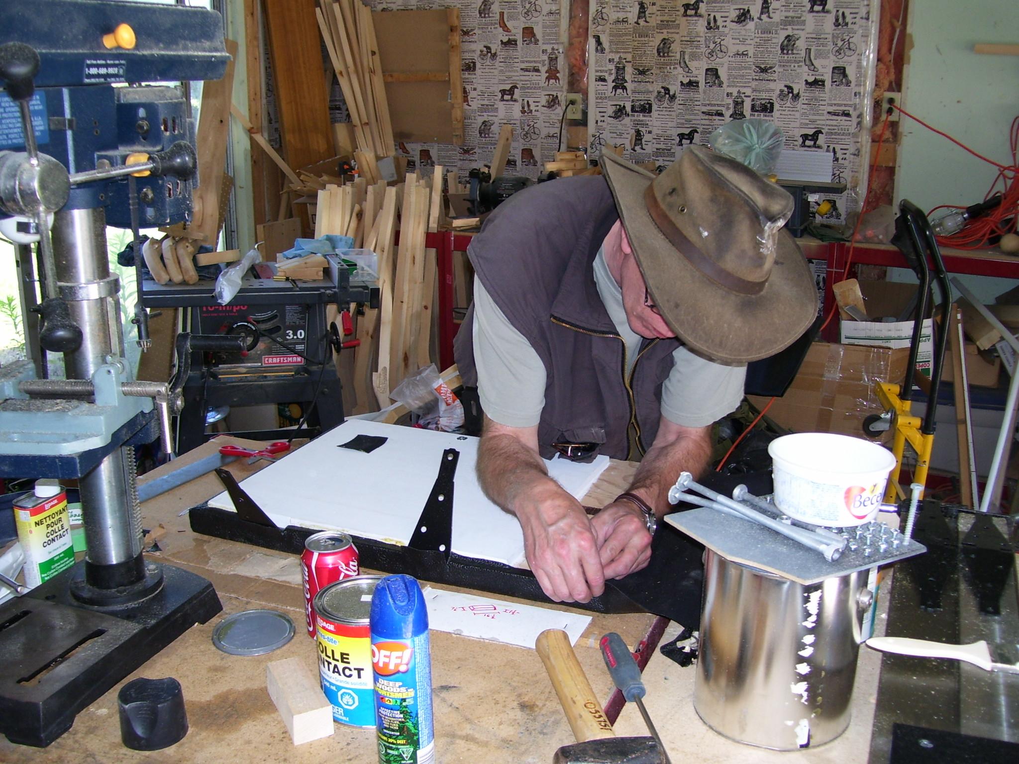
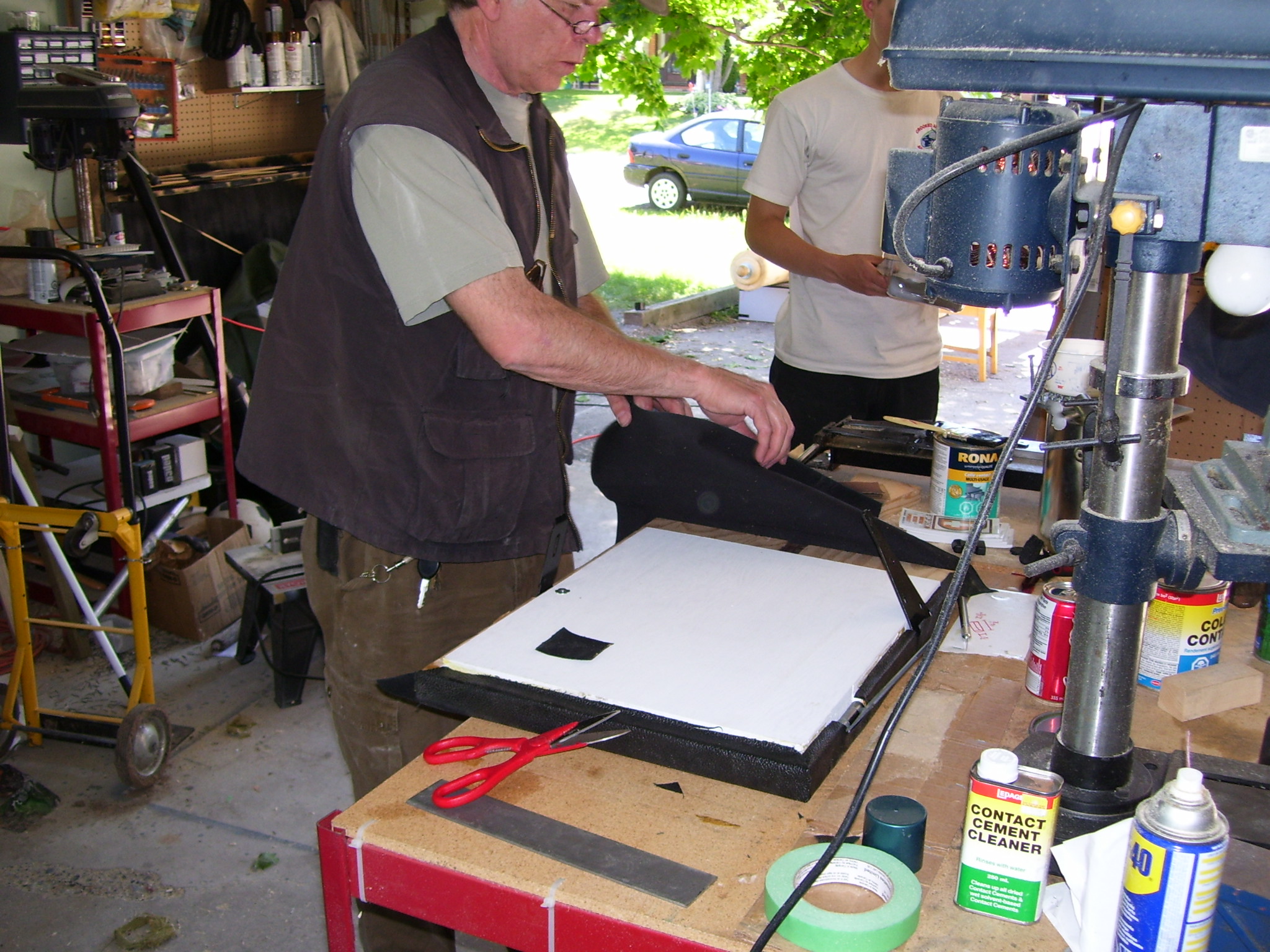
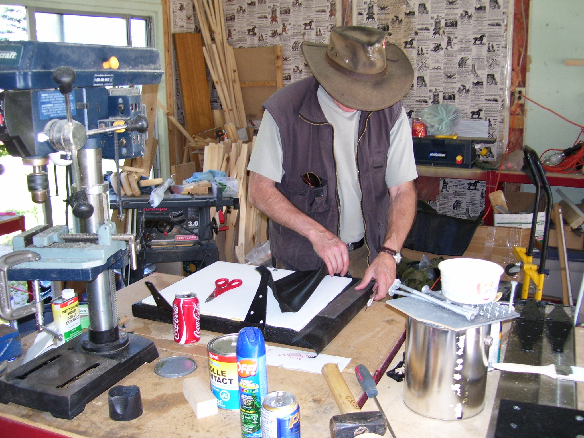
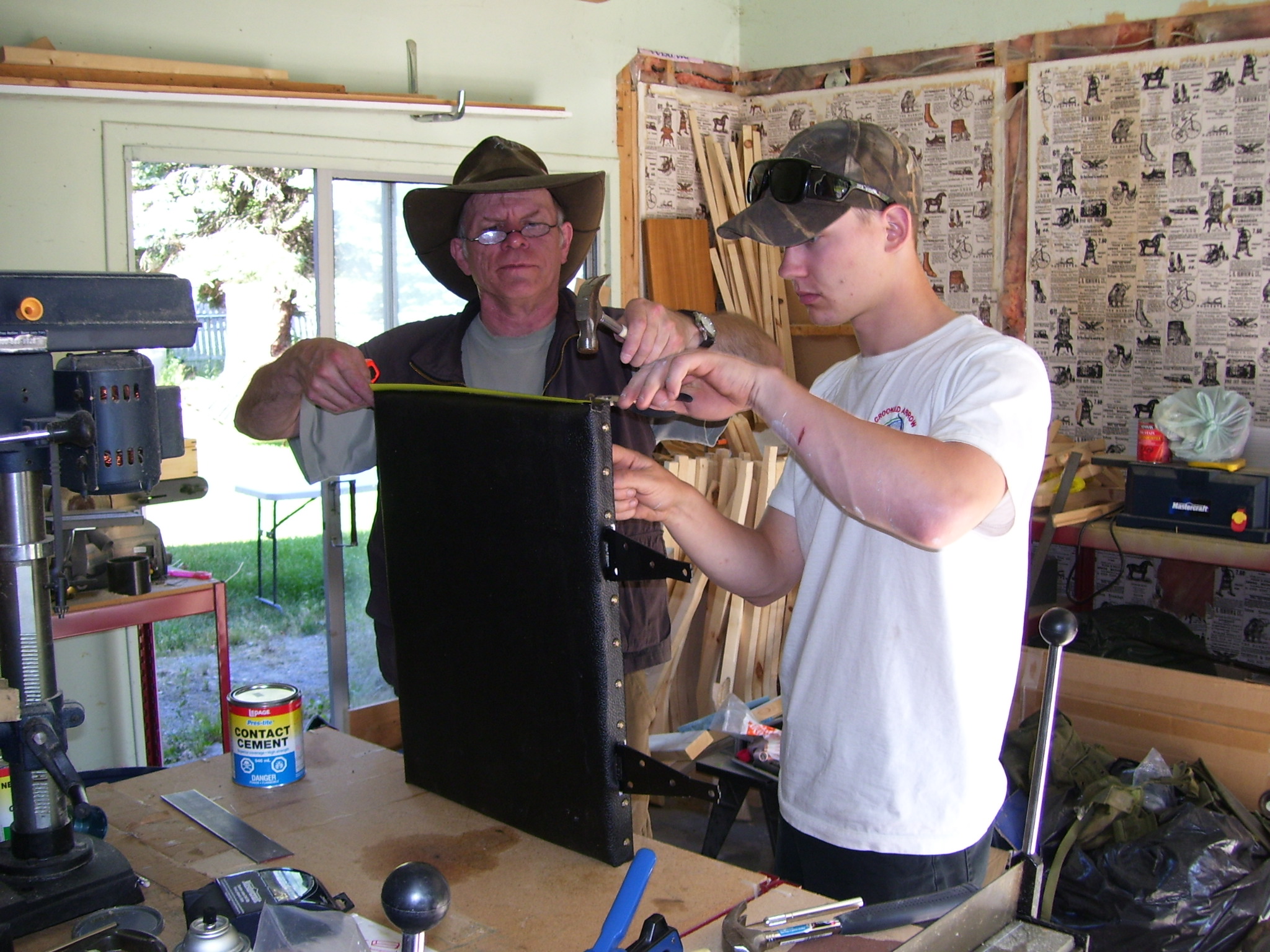
The padding was made from dense carpet underlay, two layers, attached to the cover with contact cement. The covering, a rubberized cloth-backed material (tolex), also fixed with contact cement, covered the padding. A row of tacks completed the cover assembly.
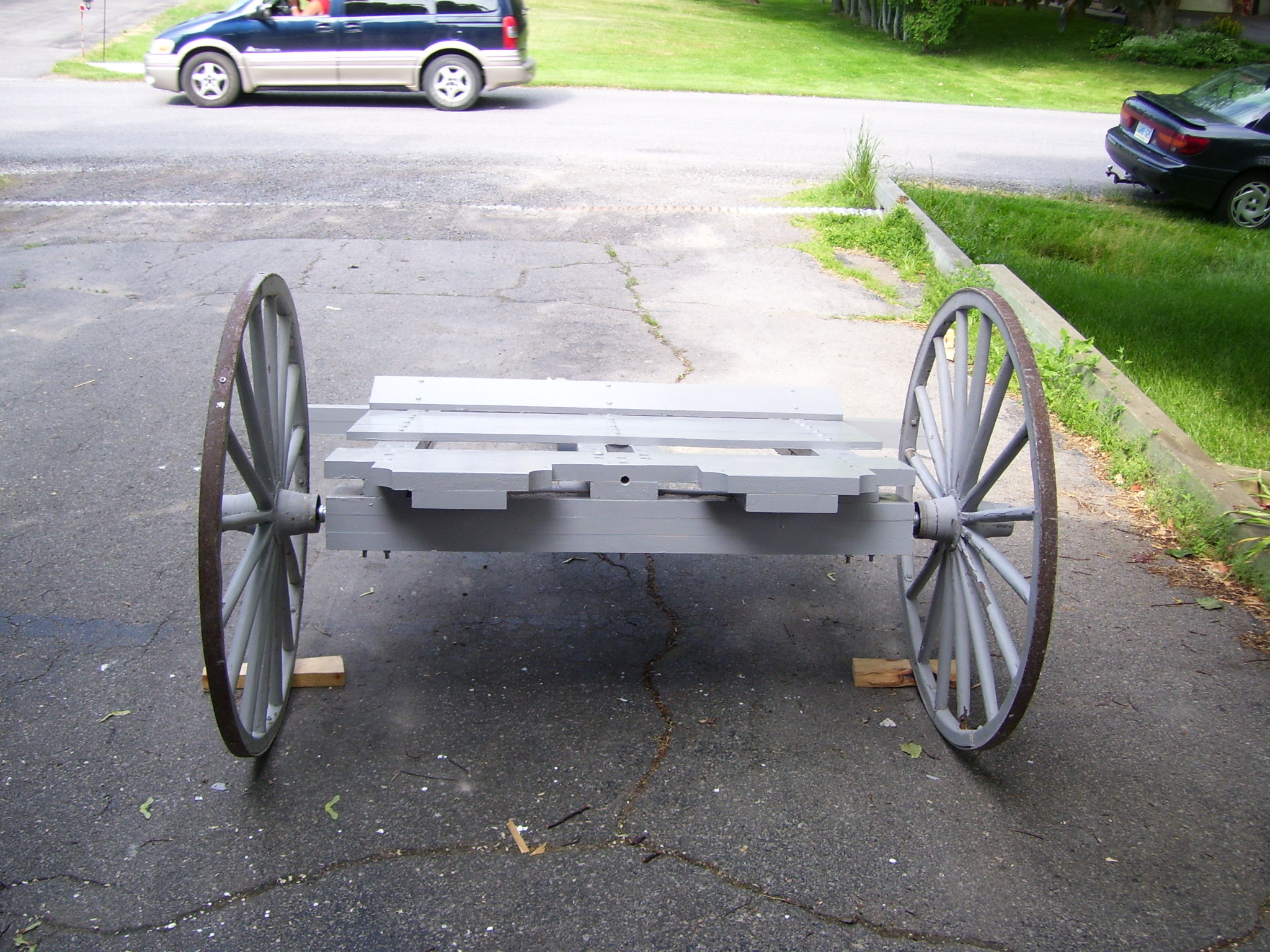
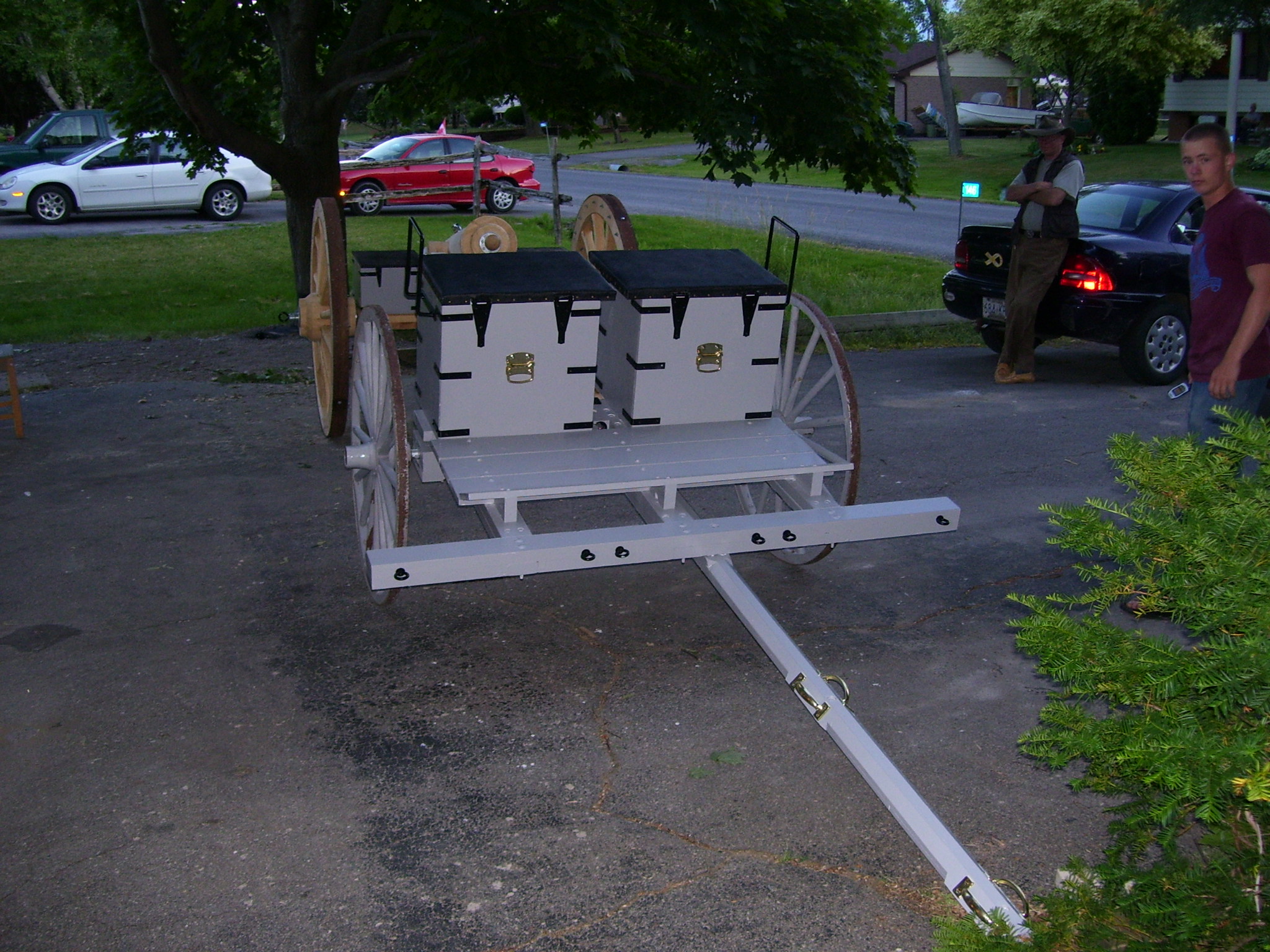
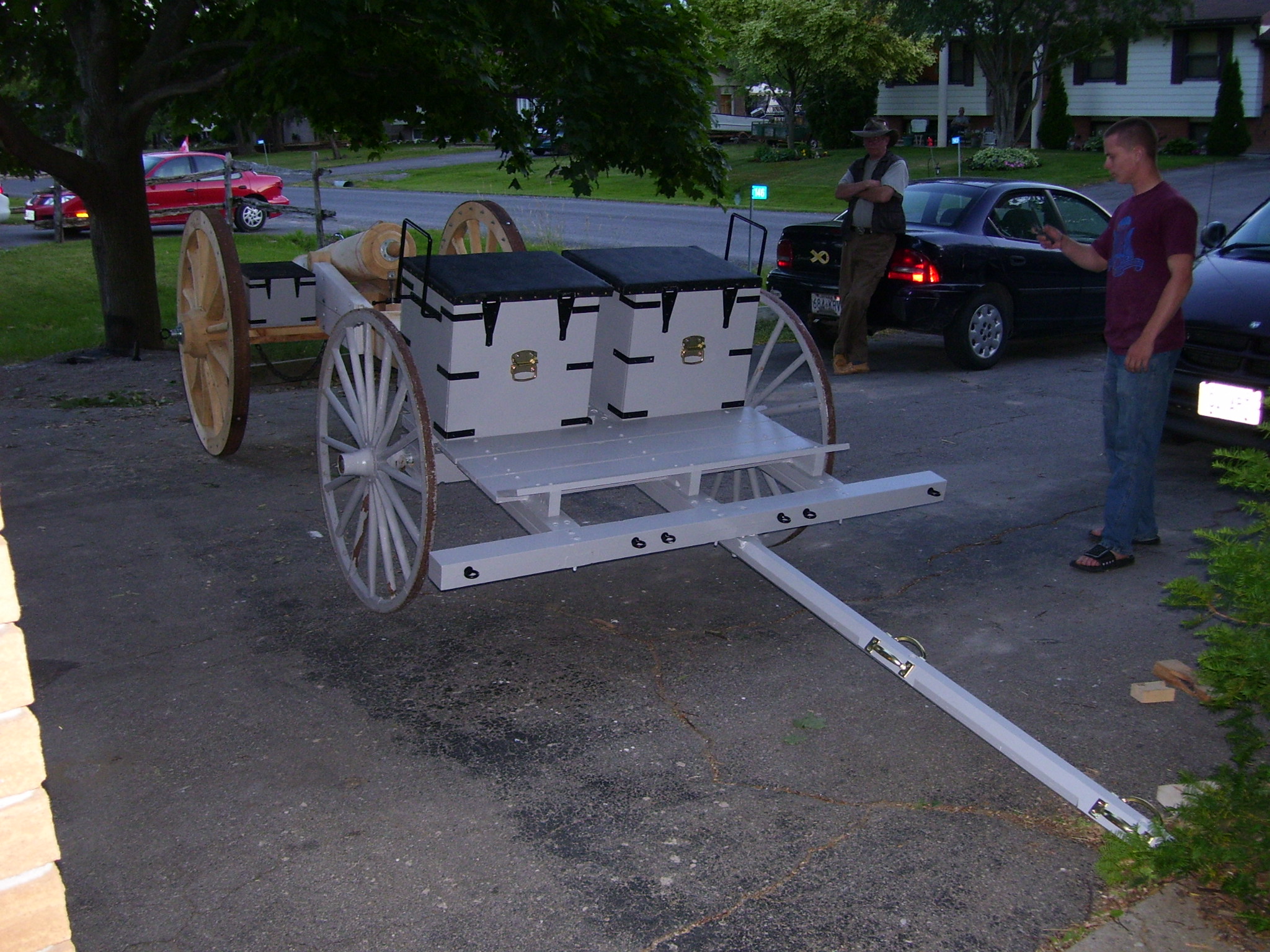
Step 6: Painting the limber
The limber was primed and painted in artillery grey.
Step 5: Outfit the limber
The limber fittings include the trail-hook and hardware for the splinter bar and the pulling pole.
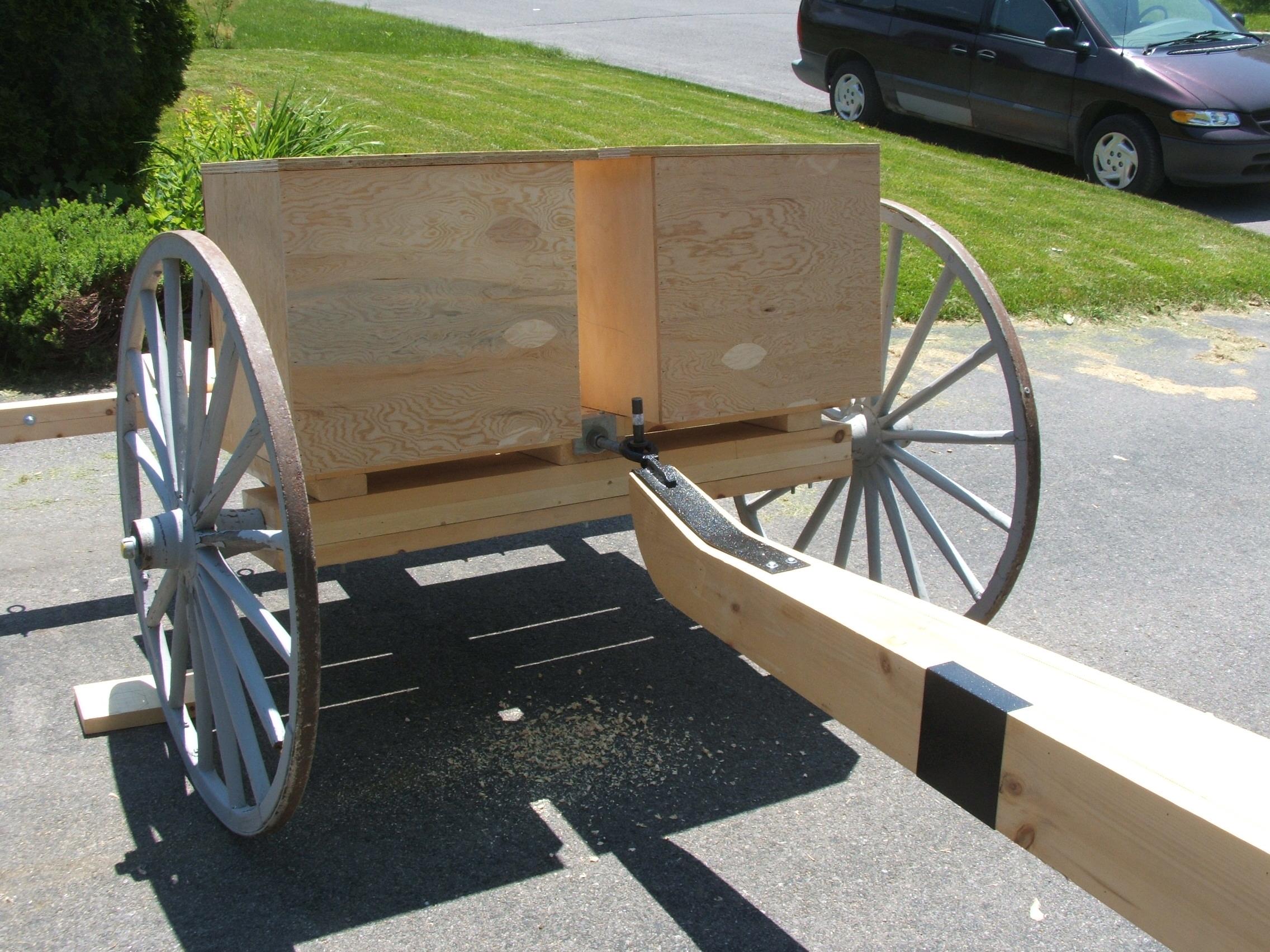
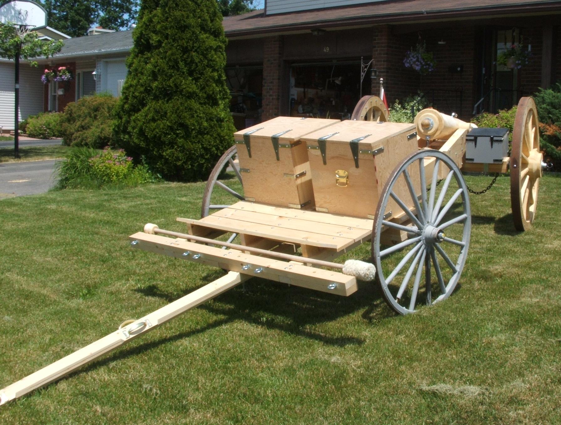
The trail hook is a large gate hinge, bolted through the limber bed, using an angle flange for extra support. The limber bed was extended back using two 2”x8” planks, trimmed to attach to the bed and form a secure bench for the rear of the ammo boxes.
A pair of hooks is installed below the ammo boxes, on the axletree, to carry the swab-buckets.
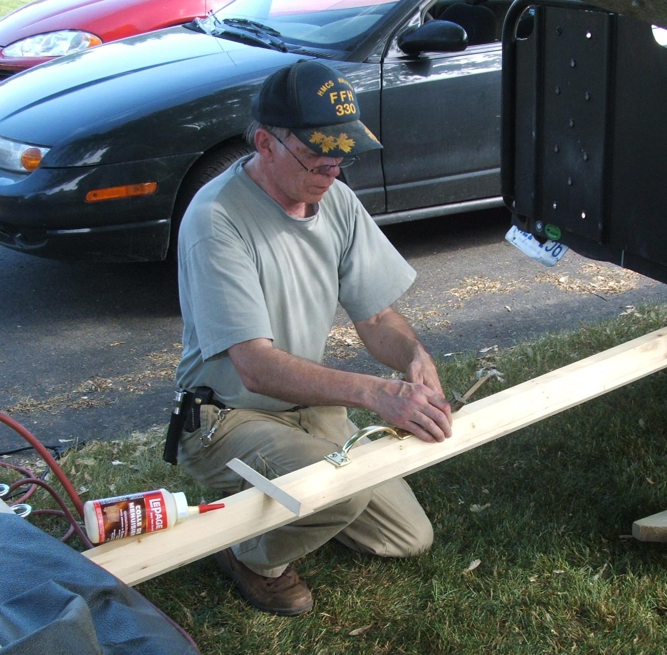
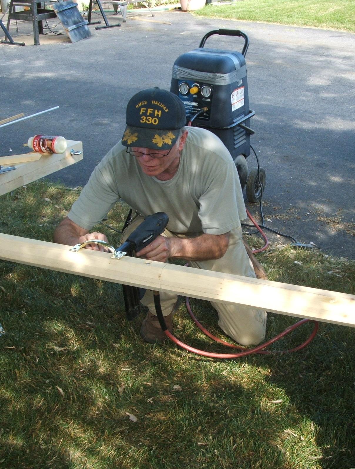
Each pull-pole was fabricated from two 2”x4” planks, with the corners removed to form an octagon pole. On the short one, portions of the removed material were used to enlarge the area where the handles, four in total, are attached. The longer pole used two shaped crossbars made from a 2”x4” plank.
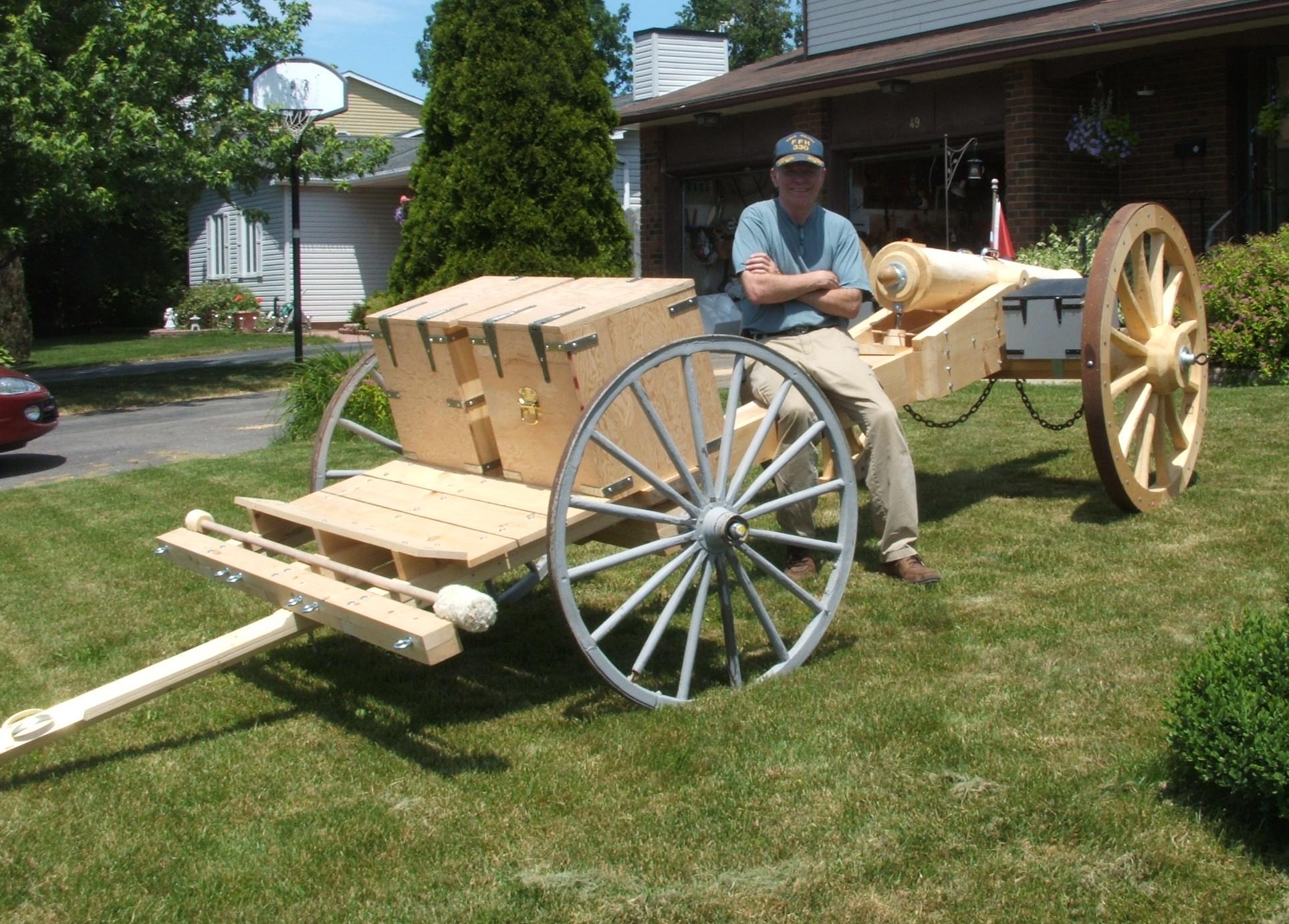
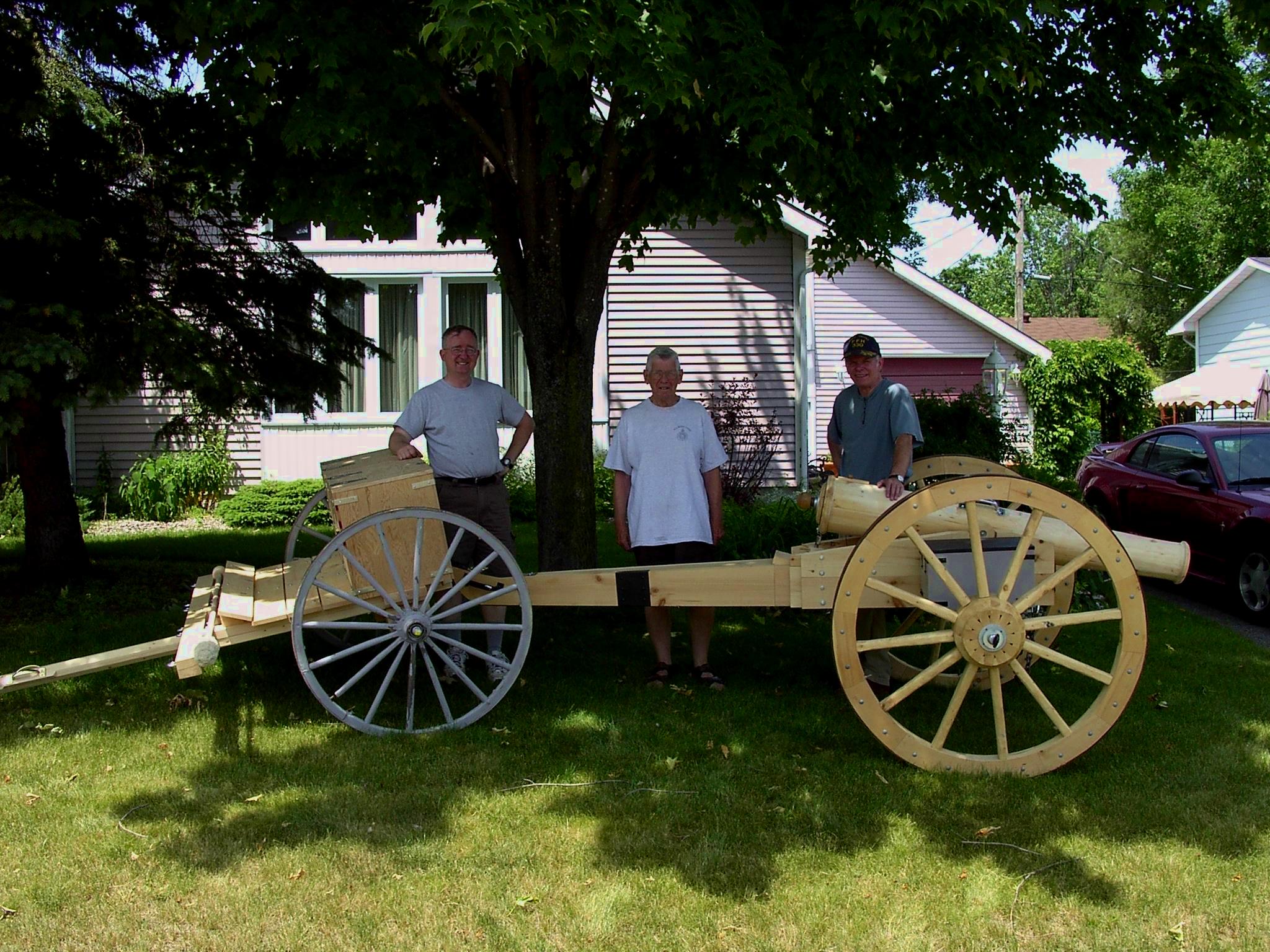
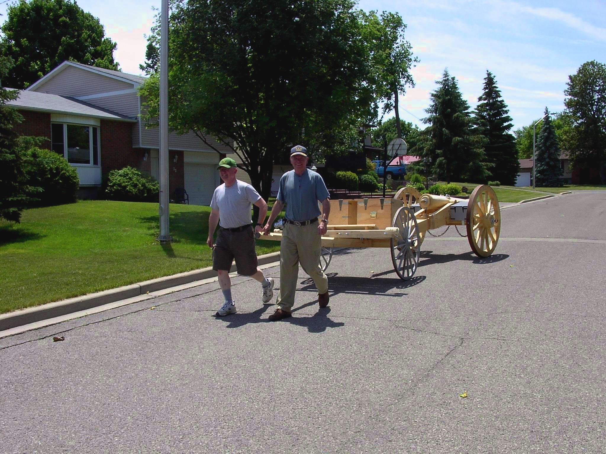
Step 6: The Limber
The completed limber.
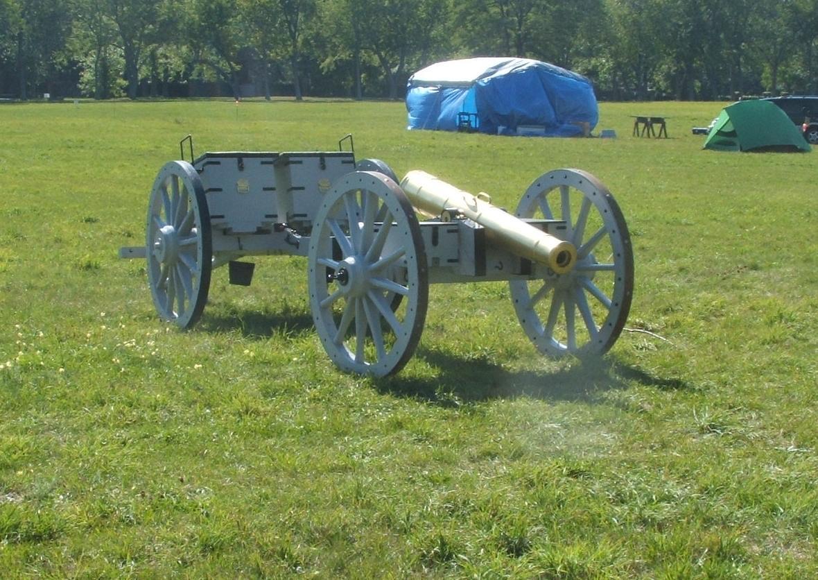
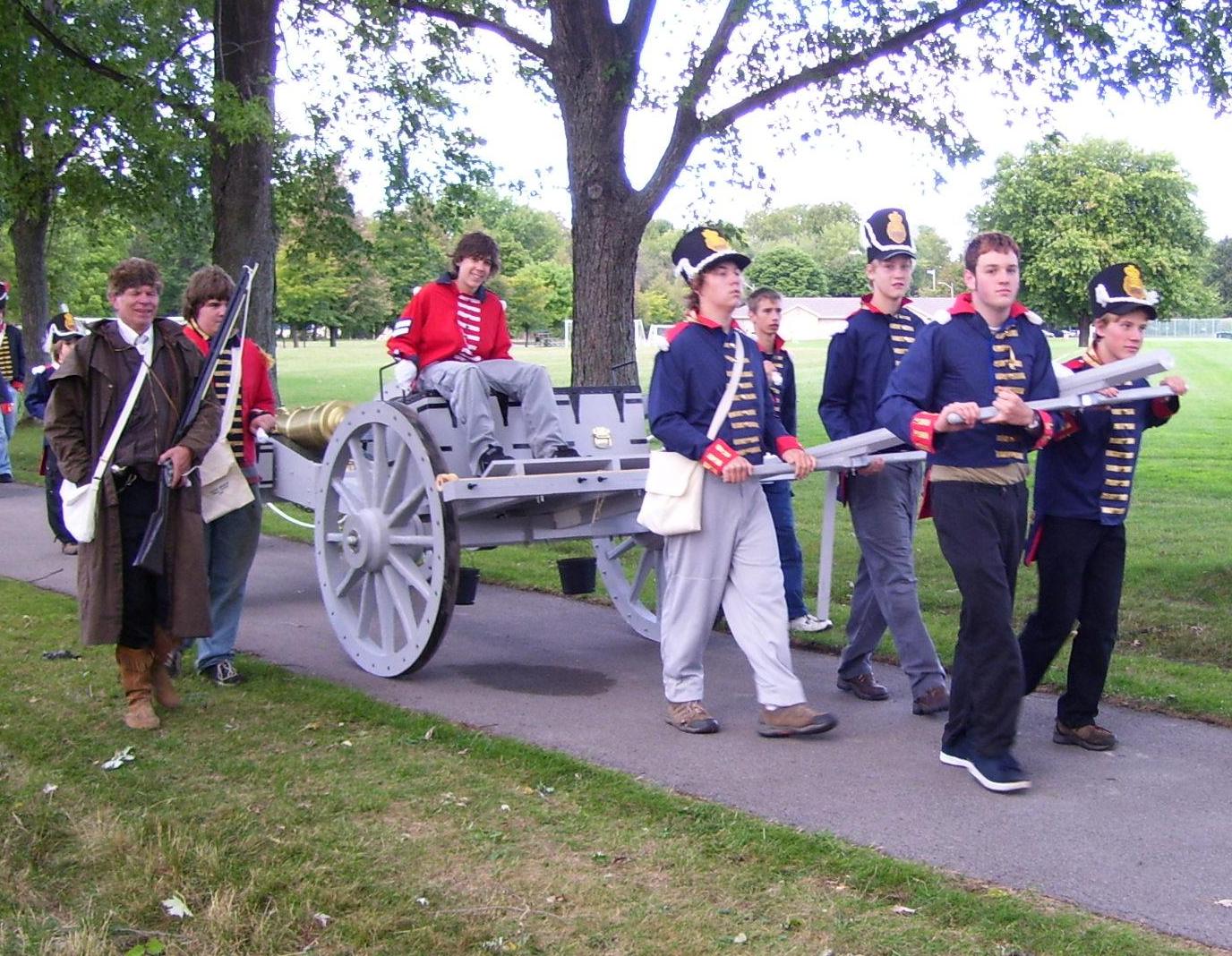
The gun and limber were given a thorough workout during the Scouts re-enactment of the War-of-1812 battles around Fort George, Niagara, Ontario, September 15/16, 2007. It performed exceptionally well, even across country, including with riders. It proved easier to move the gun with the limber, which carried the weight of the trail.
A very satisfying project…
![]()
All pages are copyrighted © 2001 Maxwell J. Toms. All
rights reserved.
Information in this document is subject to change without notice.
Trademarks or registered trademarks of any products or companies referred
to herein are property of their respective companies or mark holders.