Maxwell J. Toms
49 Julian Street, Carleton Place, Ontario, Canada, K7C 3W7
mjtoms@sympatico.ca (613) 257-7290
Artillery, Building a Replica British 9-Pounder
This project came about as a result of a discussion wirh Scout Leader Terry Honour regarding his efforts to provide suitable artillery for the War of 1812-14 re-enactments undertaken by his and other scout troops every September at Fort George, Niagara, Ontario. My suggestion that it might be possible to enclose his ‘potato gun’ in a wooden shell shaped like a Napoleonic era smooth bore started the ball rooling.
Since, come from Newfoundland and Terry’s troop represented a grenadier company of the 1812 Royal Newfoundland Regiment, I was ‘honour’ bound, pun intended, to help. During research of the regimental history, I was surprised to learn the contribution by the Newfoundlanders in these battles, first their widespread use, and in their skill, dedication and resourcefulness, earning honourable mention by British Officers on many occasions. This honour had to be upheld!
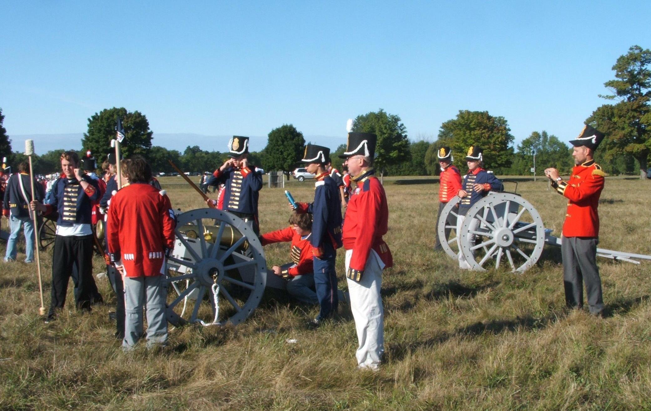
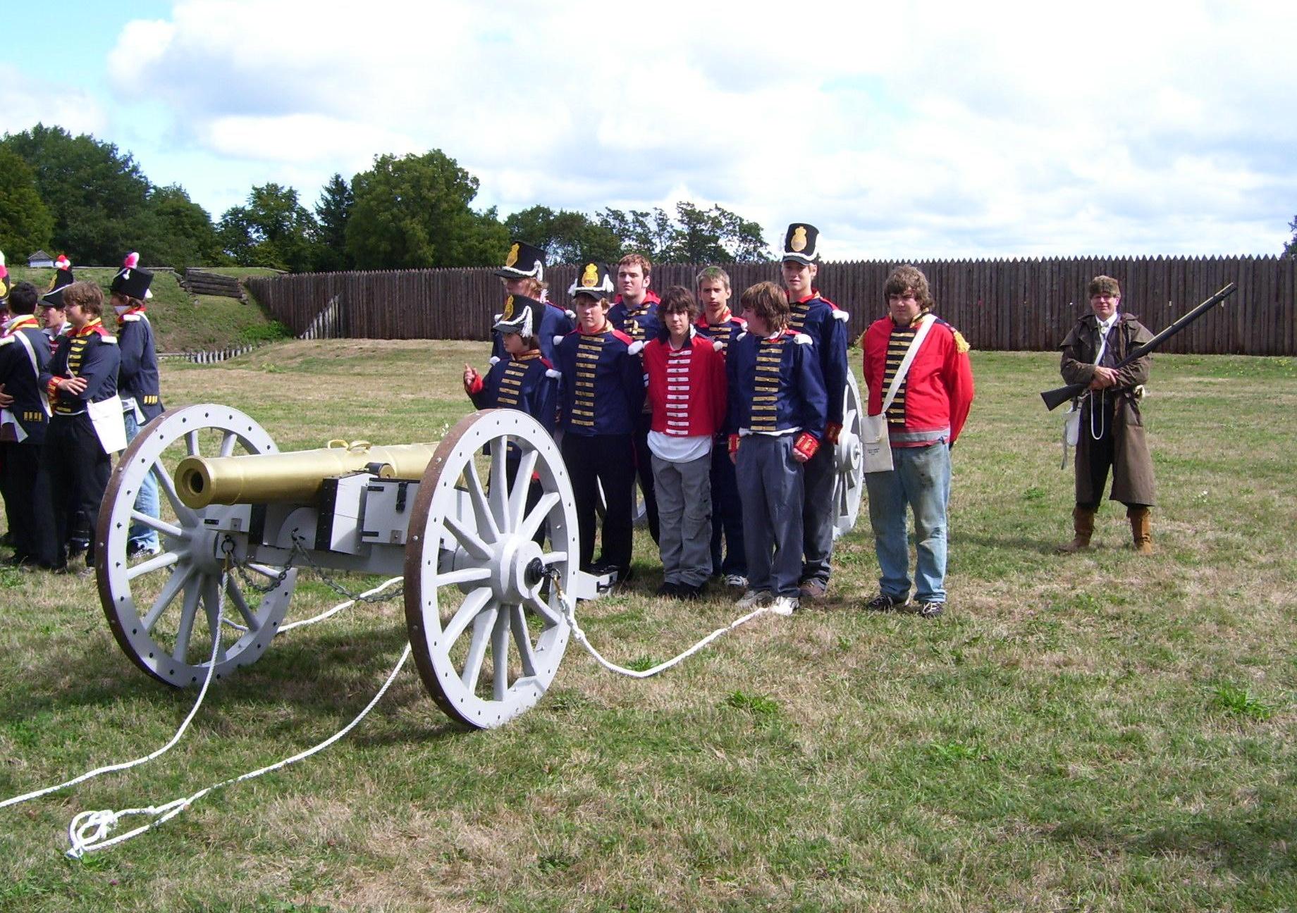
The Mission: Build a replica artillery
piece suitable for War of 1812-14 re-enactments
Our requirement was simple. The field piece needed to look approximately like a 9-pounder brass cannon of the period, and had to be able to simulate firing. Thus, after a thorough search of local hardware stores for suitable materials, we elected to construct the gun as a wooden shell, enclosing a ABS 'potato' gun. This involved construction of new wheels and trail using only available materials and tools.
There was no attempt to make a museum piece, but rather a reasonably correct looking gun that could be easily manoeuvred and safely fired by the Scouts & Venturers.
The propellant is hairspray or deodorant, set off using an electric barbeque lighter. The gun is very much a replica, but the "Bang" will be real! However, like all volatile materials, there can be danger. Note the warning below!
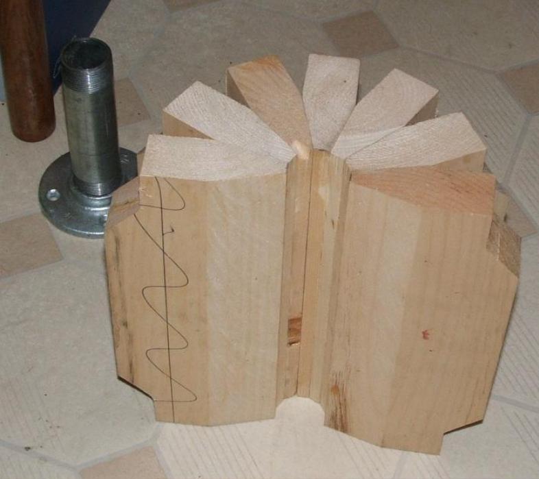
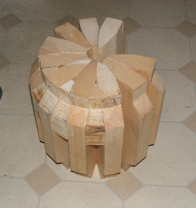
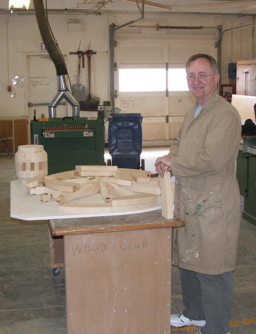
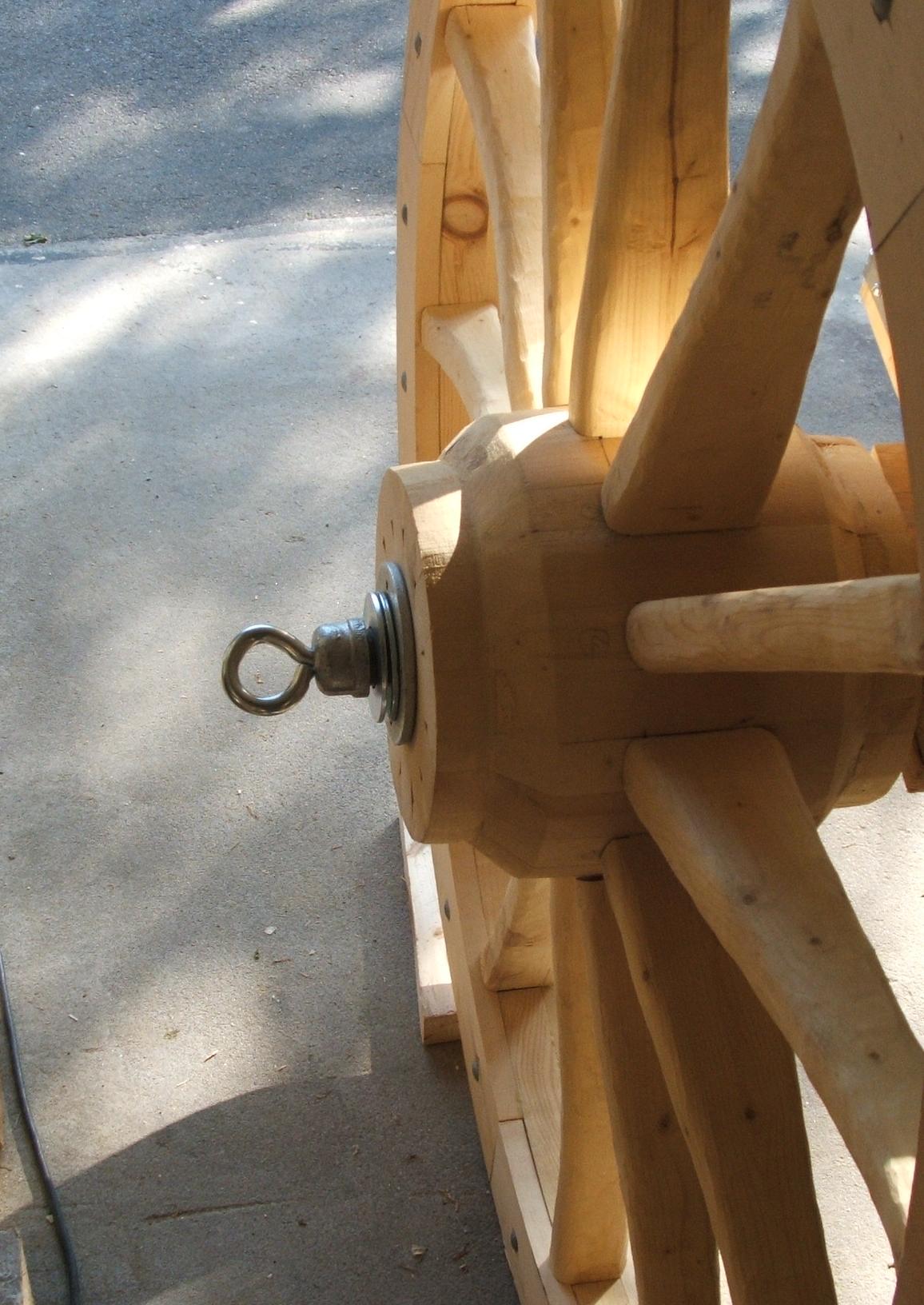
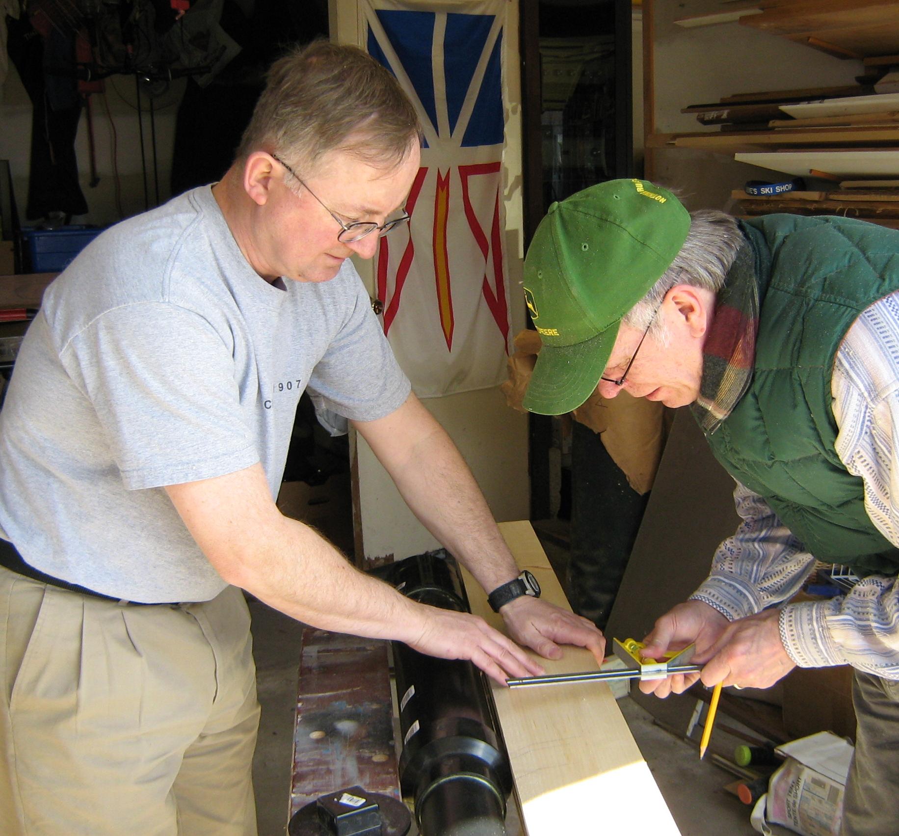
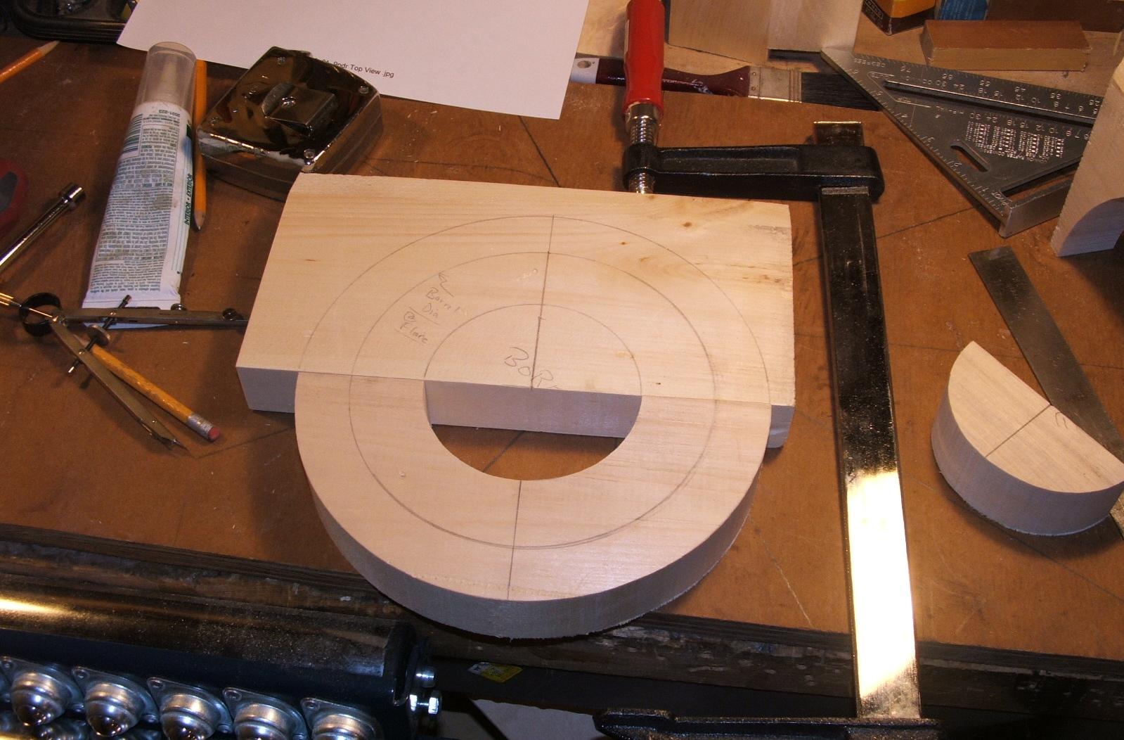
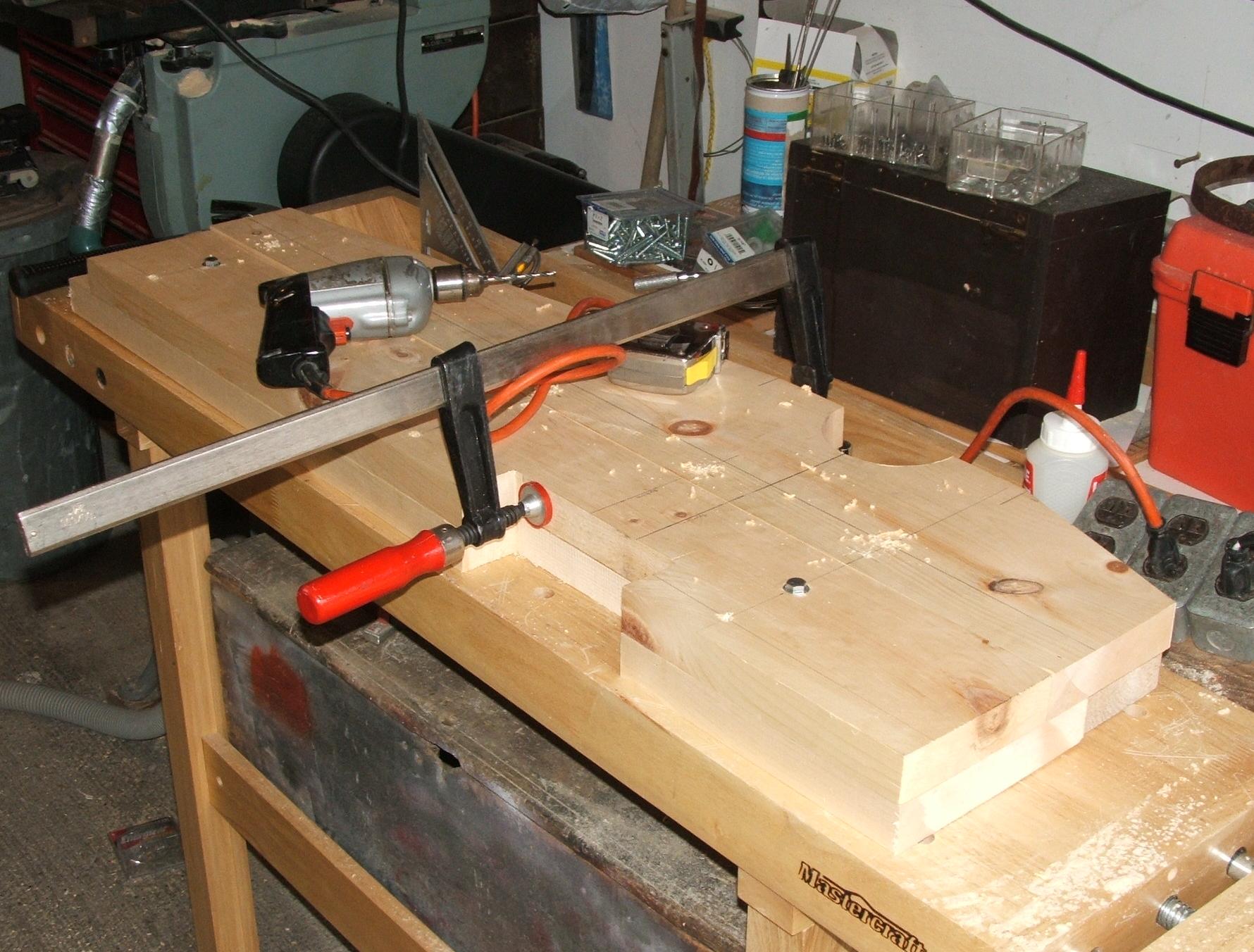
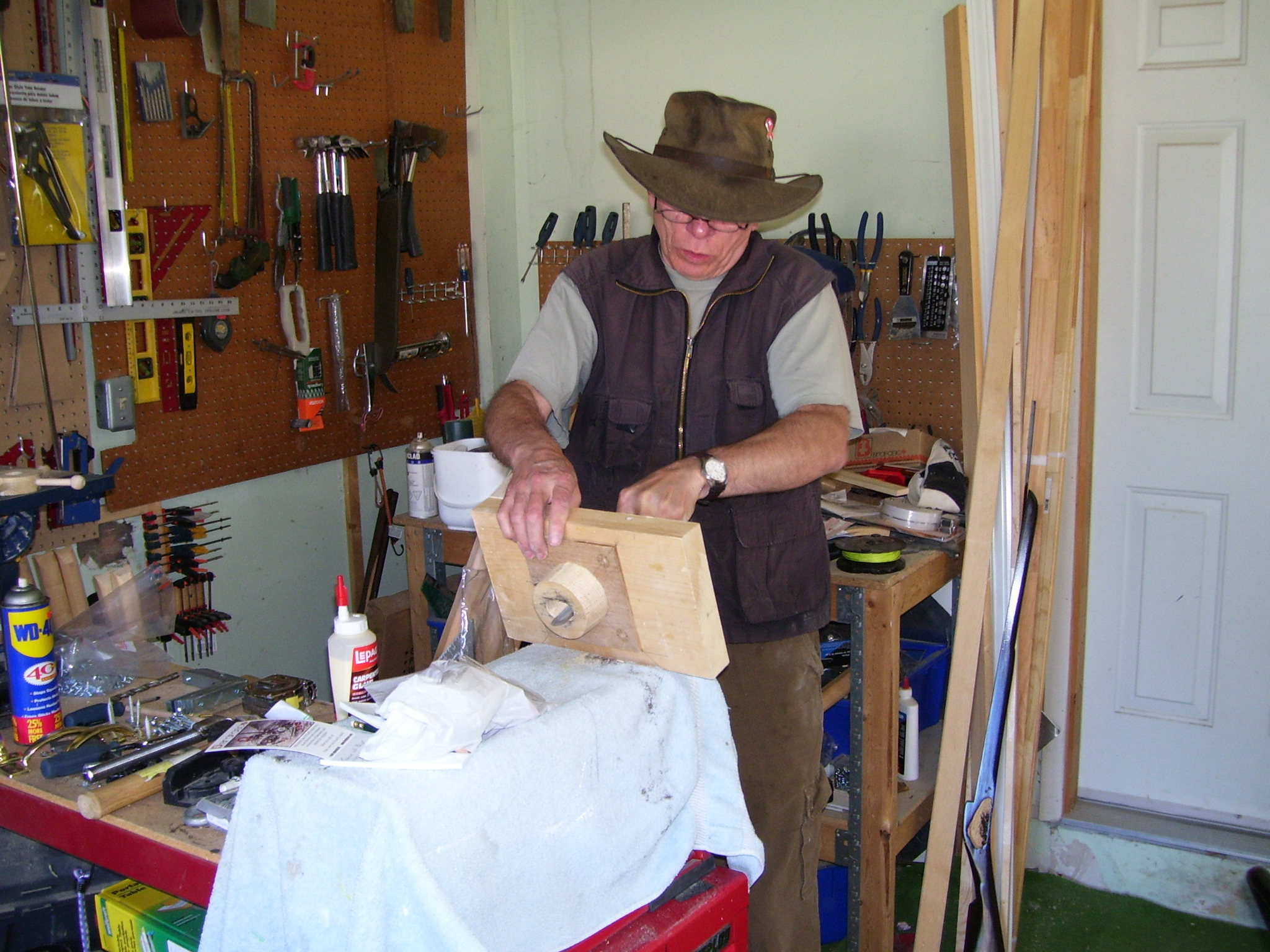
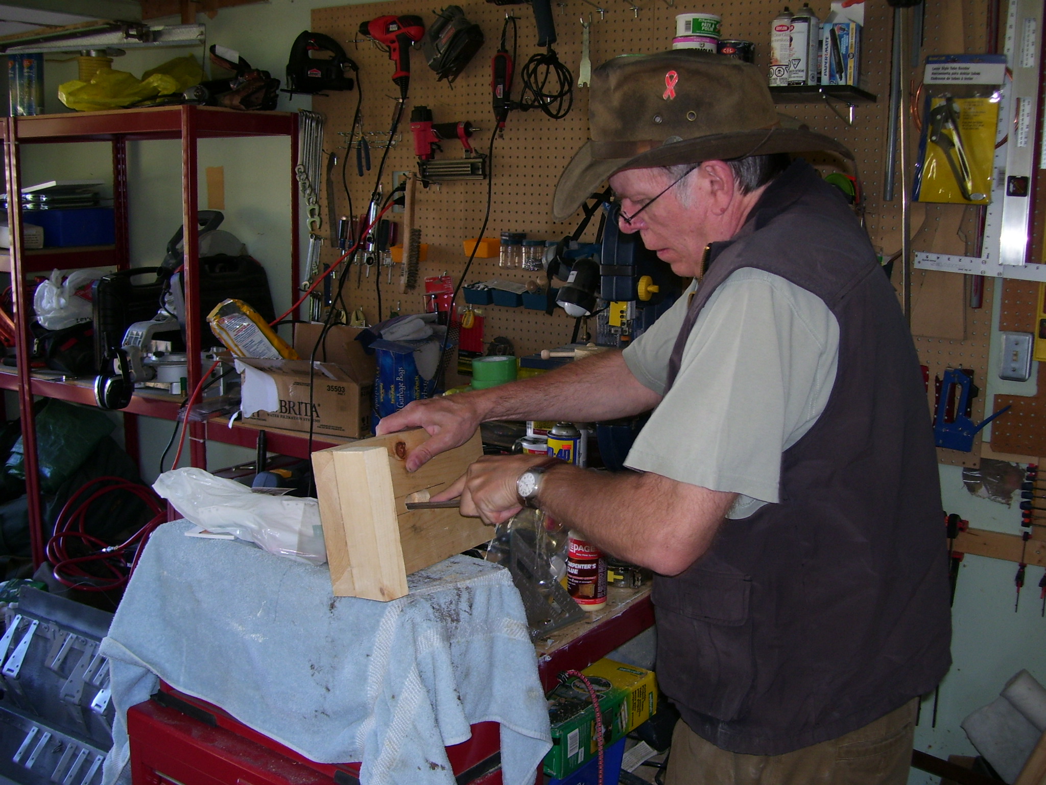
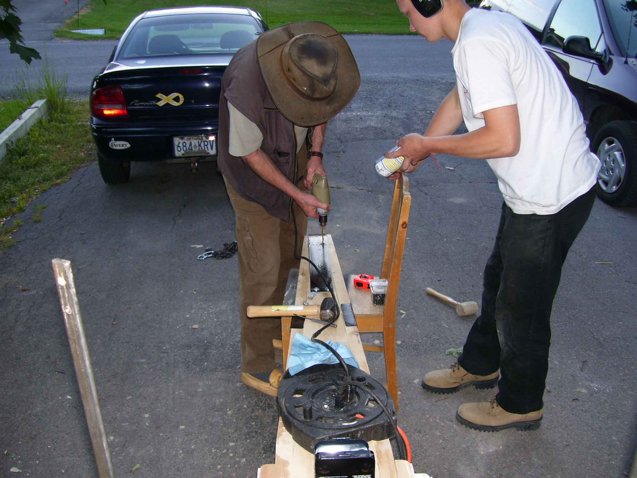
Step 1: Build a wheel hub
Construction of the wheel started with a hub,
fabricated from pieces of wood, scraps mostly, 30-degree sections
laminated, glued and nailed together. The spaces between the sections are
filled with a small wedge, leaving a hole that forms a mortise for the spoke.
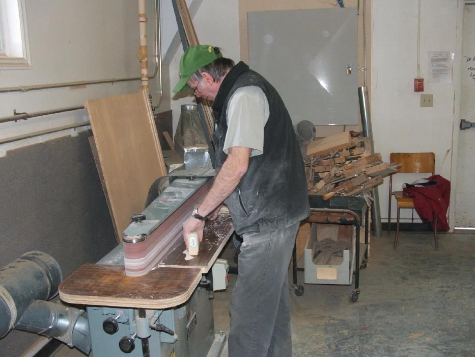
Construction is quite simple, but one needs to be reasonably precise with
cutting and fitting.
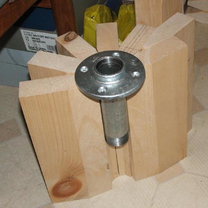
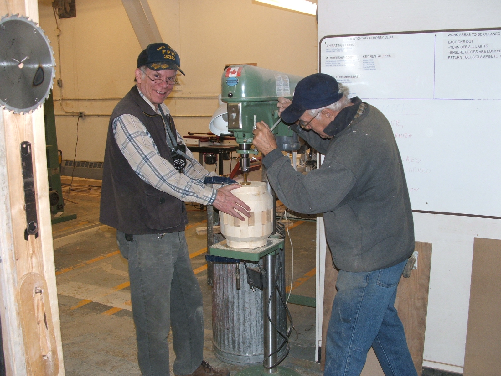
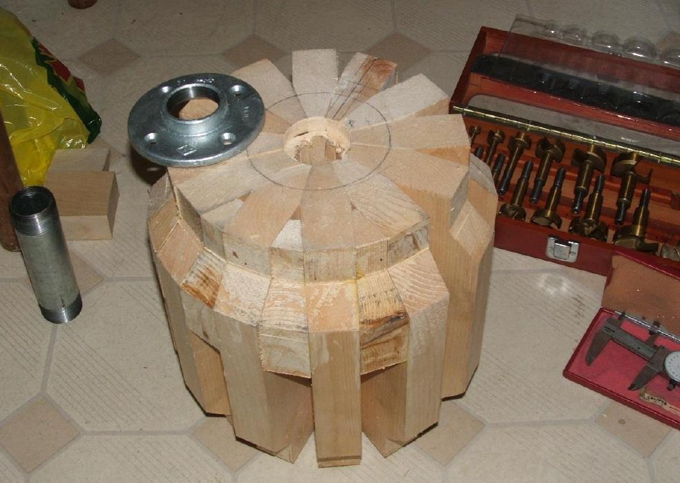
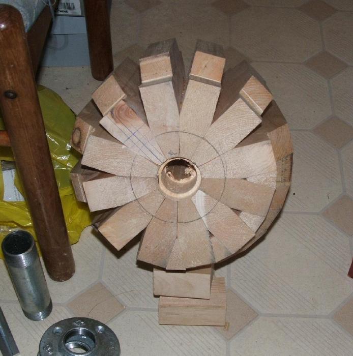
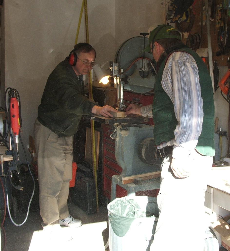
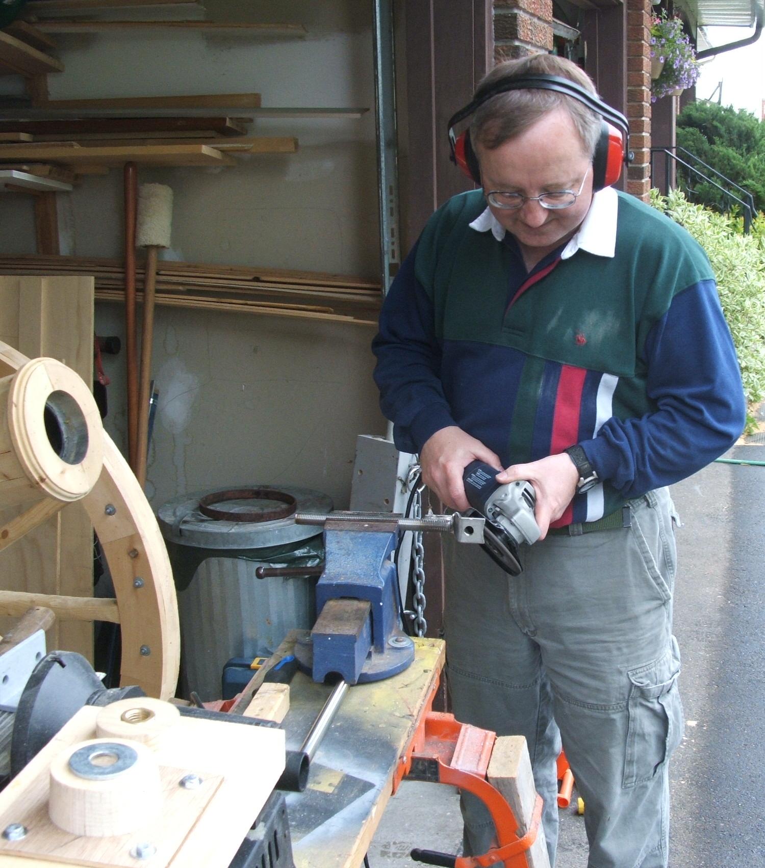
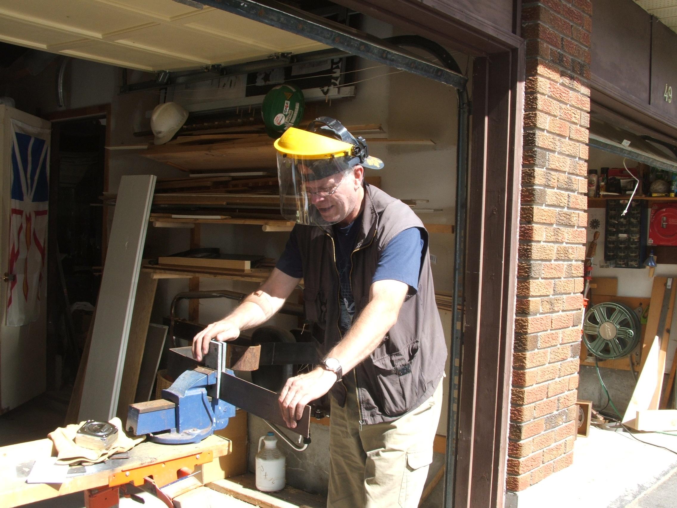
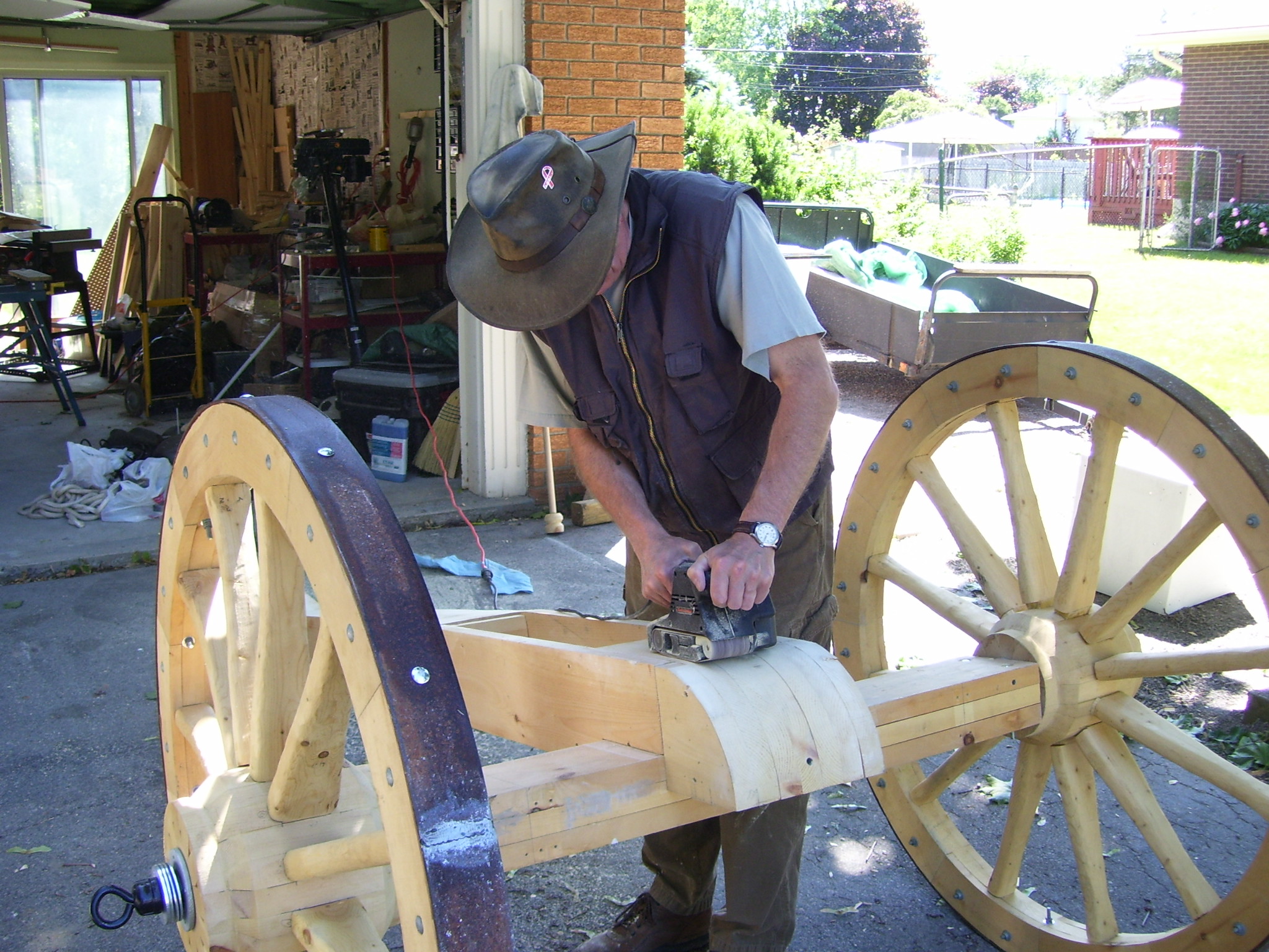
For bearings, we used a 1.25” steel pipe flange with a short nipple installed. This almost exactly fits a 1” steel pipe used for the axle. The Hub is bored to fit the bearing assembly, which can be simply screwed in. When greased, these bearings work very well and should stand up to the rigors of re-enactments for years. They will not stand up to towing!
An axle jig, a short piece of 1” pipe clamped to a workbench was used to allow the hub to be rotated for sanding.
Steel bands for the hub are yet to be installed.
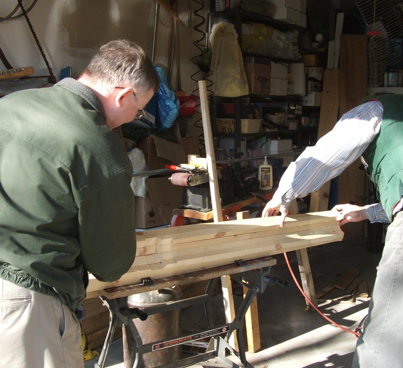
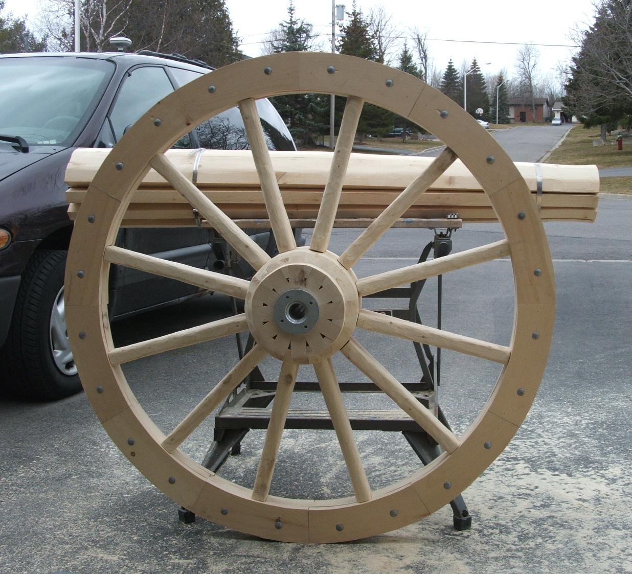
Step 2: Build the wheel
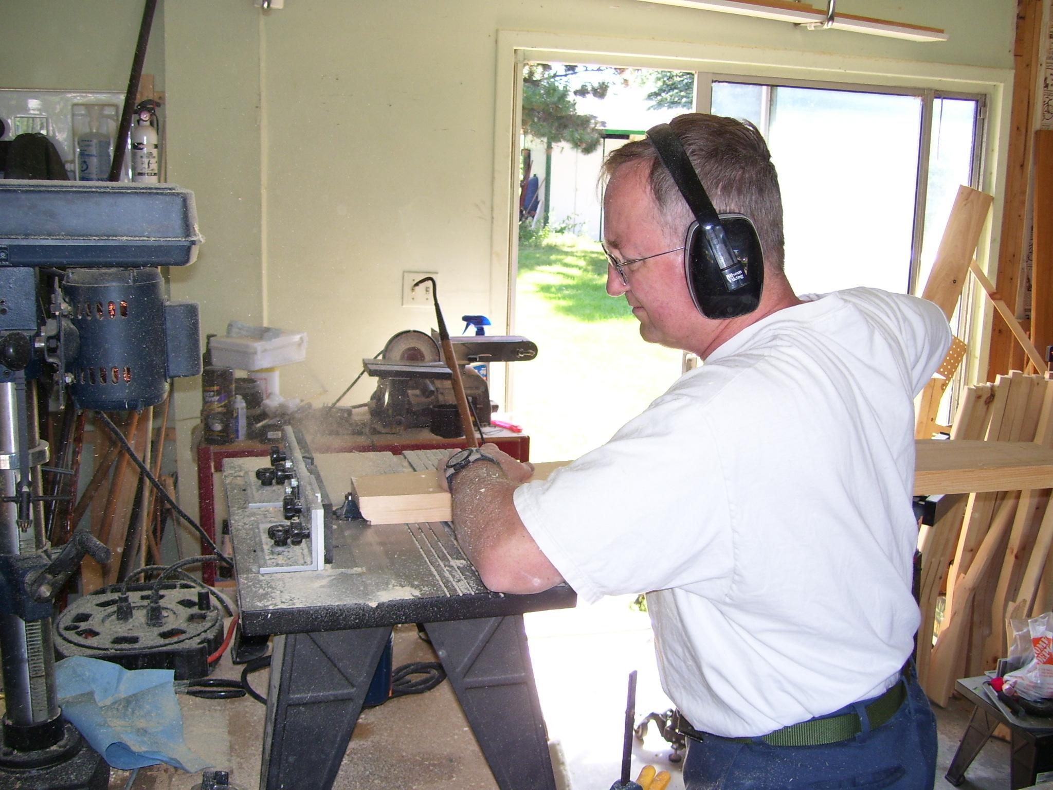
As with the hub, the wheel rim and spokes were fabricated from plank and board.
The wheel rim was assembled with 30-degree sections, cut to curve from 2x6 plank and 1x6 board each side, offset to provide a strong laminated construction. The ends of the 2x6 inner sections were notched to form a mortise for the spoke. The whole assembly was glued and bolted together.
The spokes were fabricated from 2x4 studs, cut and shaped to fit. Again, construction is quite simple, but as before, one needs to be reasonably precise with cutting and fitting.
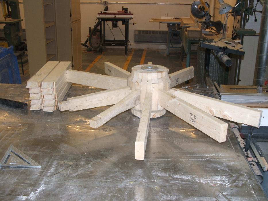
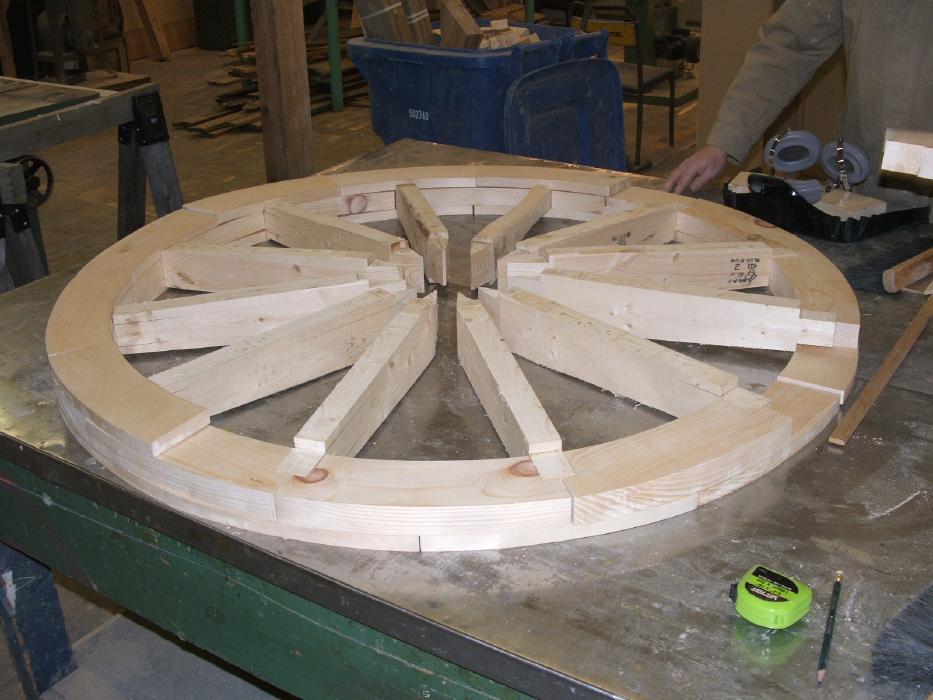
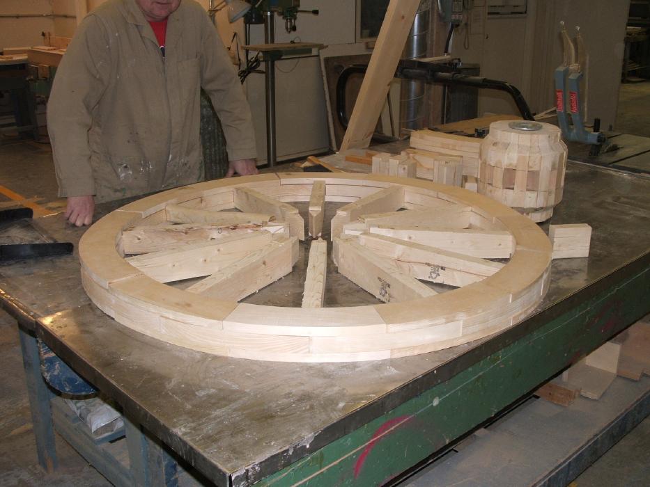
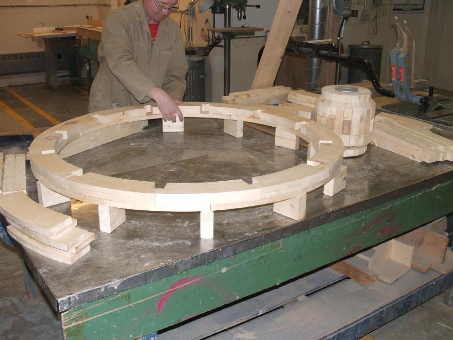
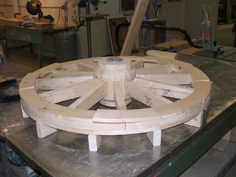
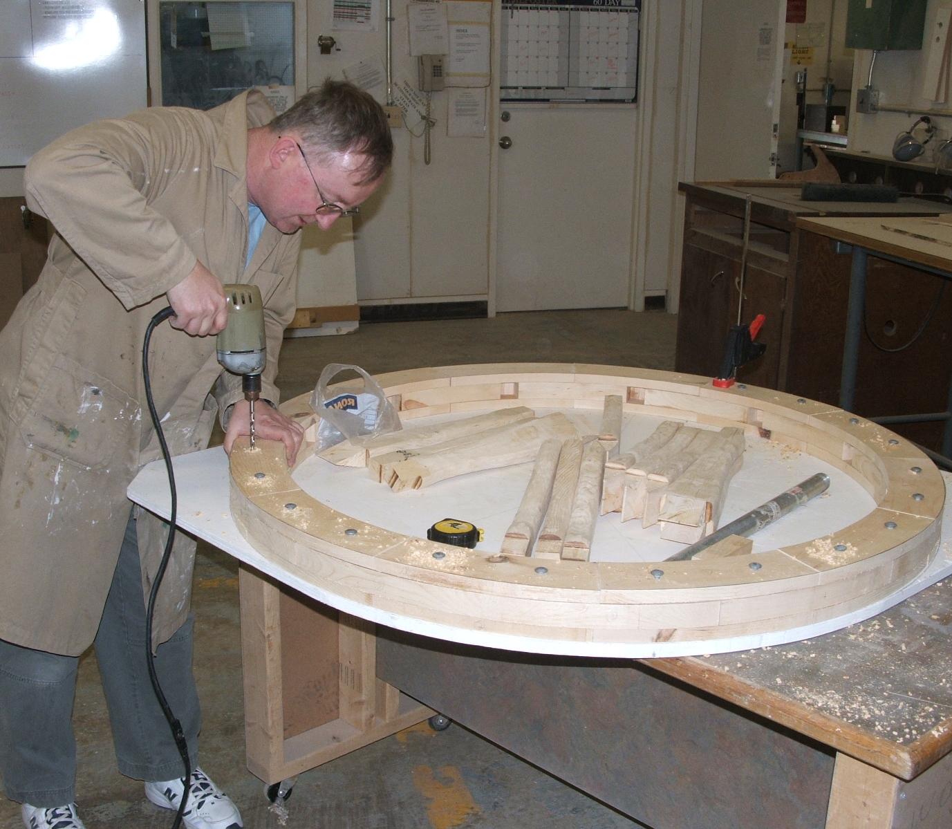
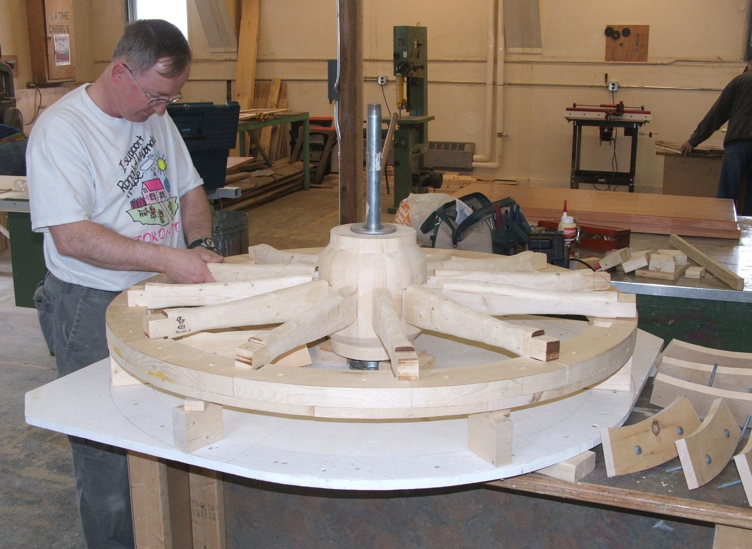
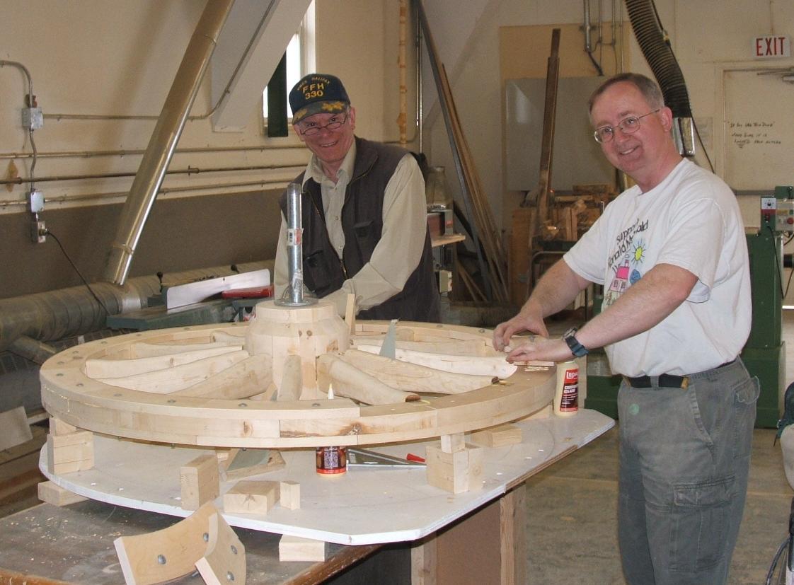
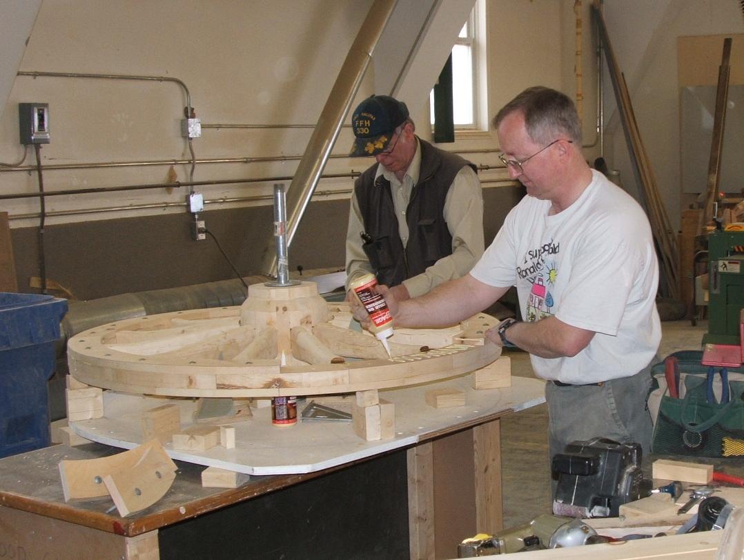
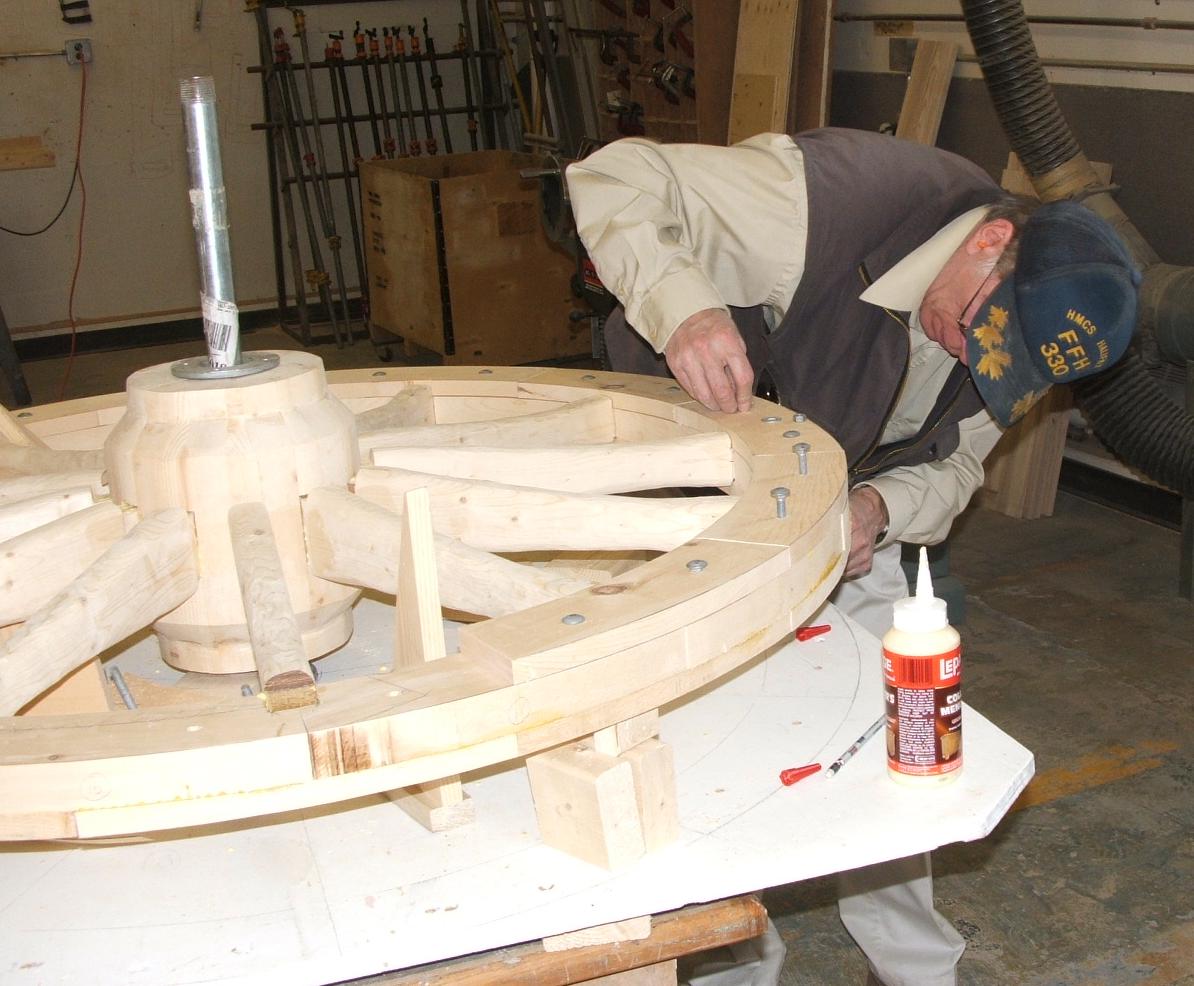
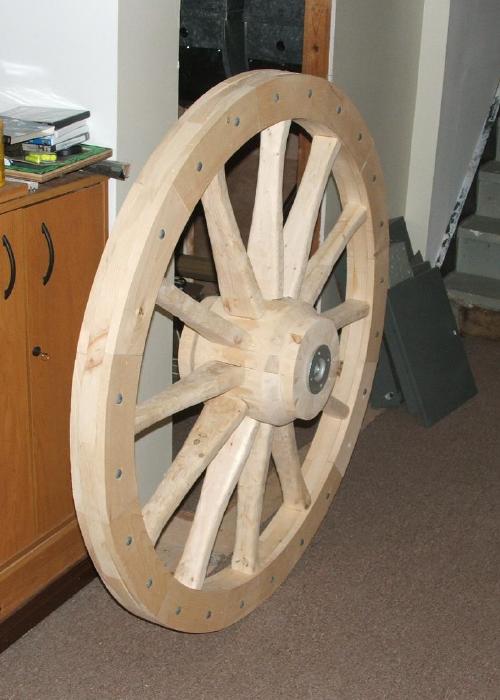
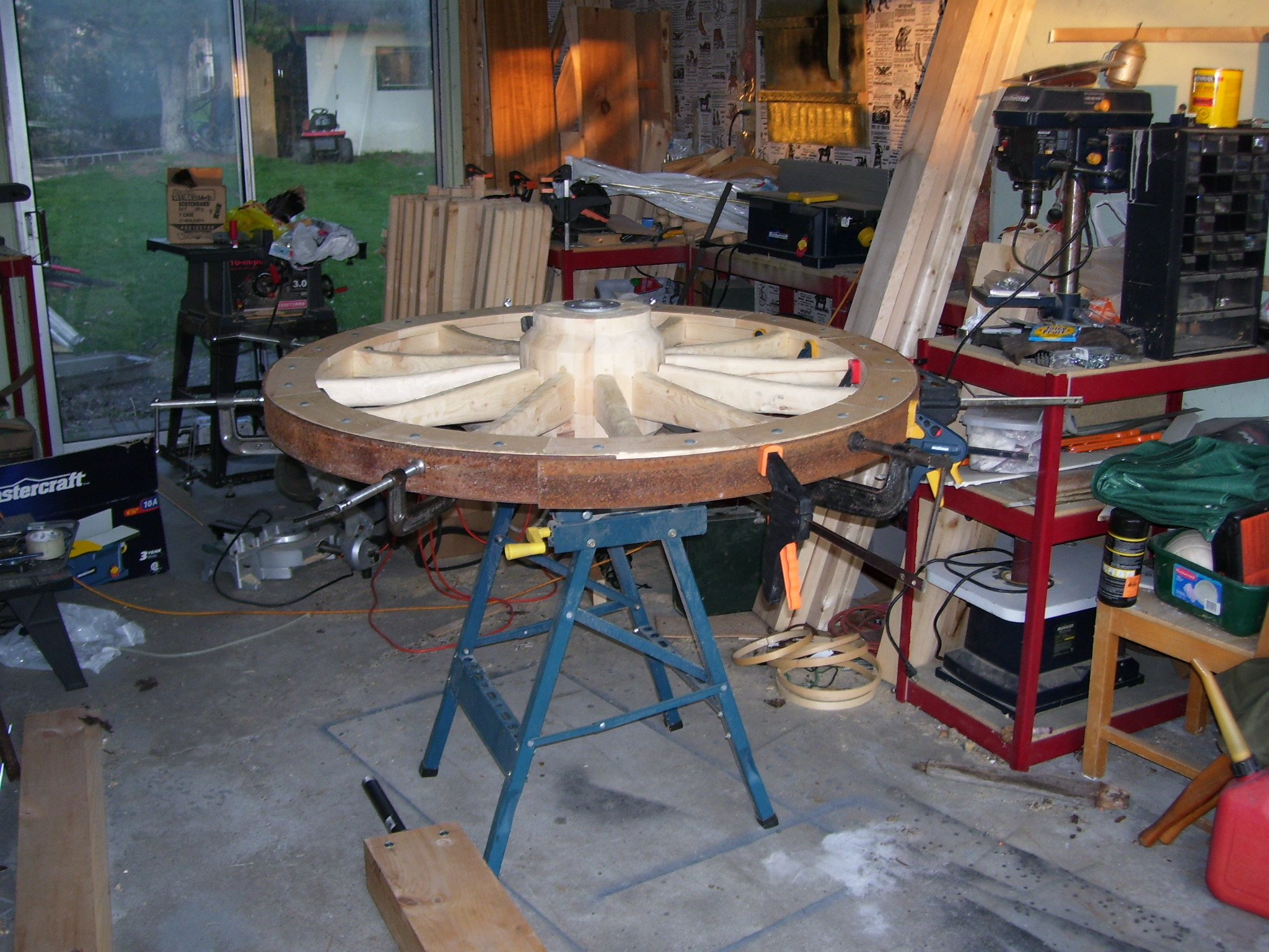
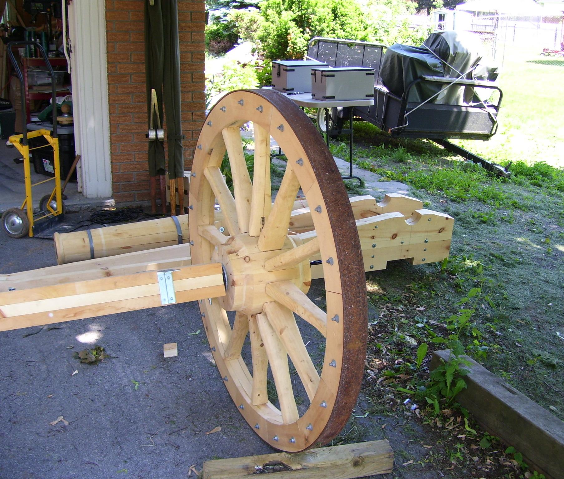
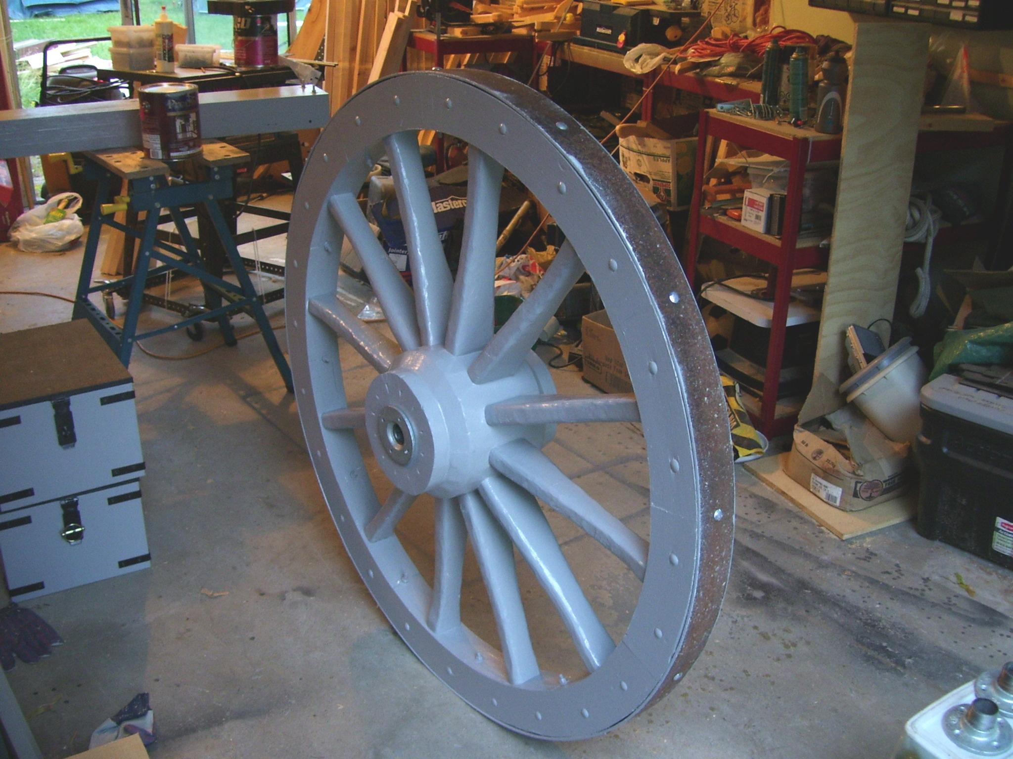
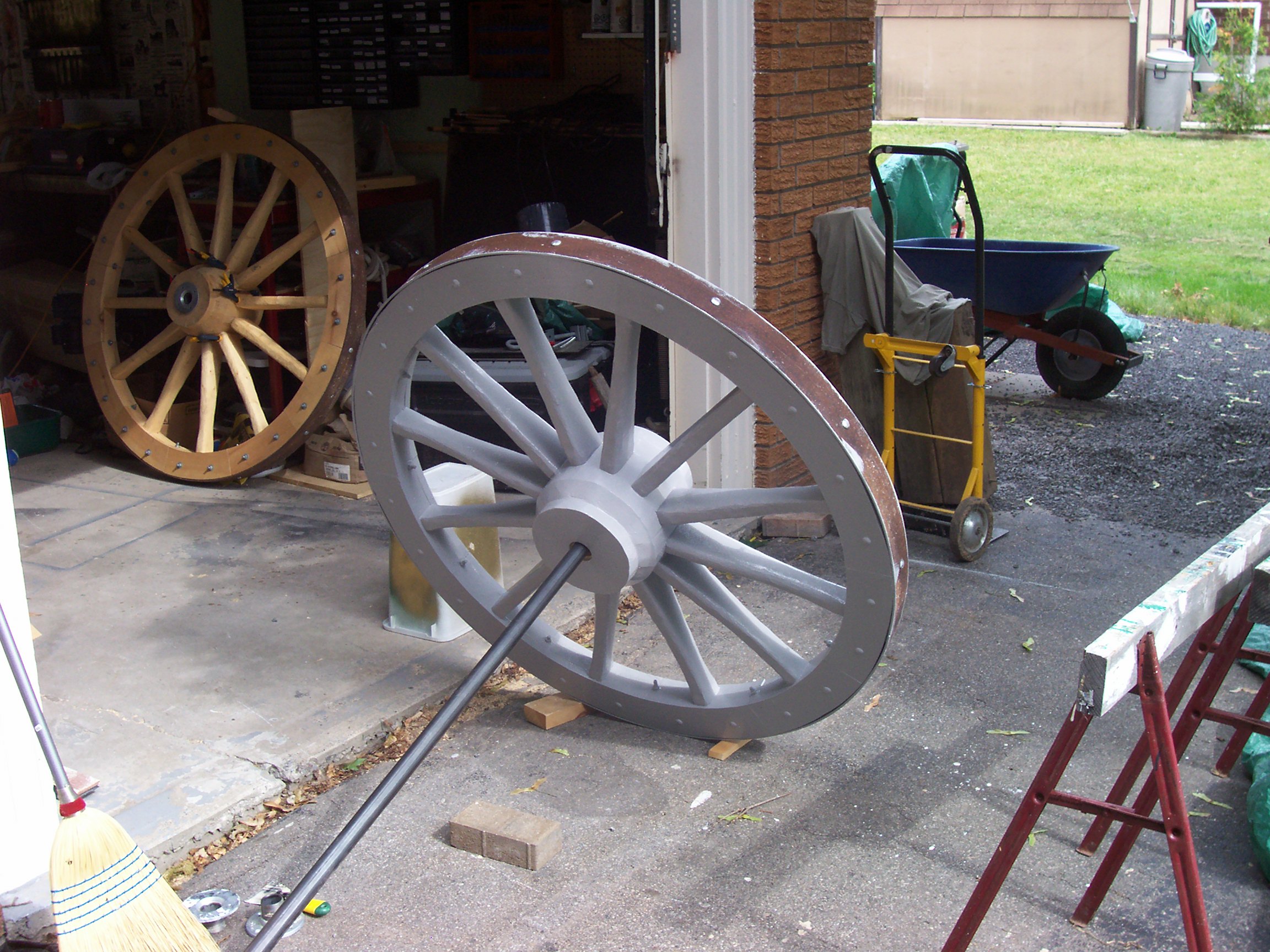
The wheel was assembled on a jig, with the rim elevated to allow positioning and fitting of the spokes. A pattern of 30-sections, with the centre and rim curve, was drawn on the jig for accurate position and fitting.
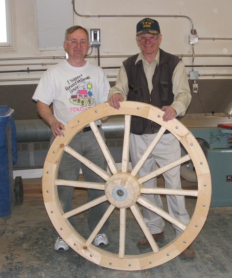
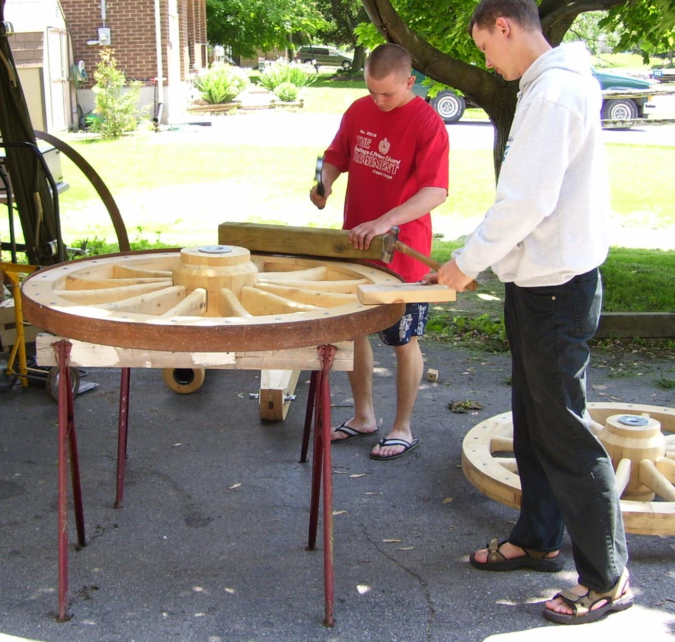
Each wheel is fitted with a steel band (tire) that is bolted to the rim. When complete, the wheel is painted a medium grey, consistent with the artillery colours of the times.
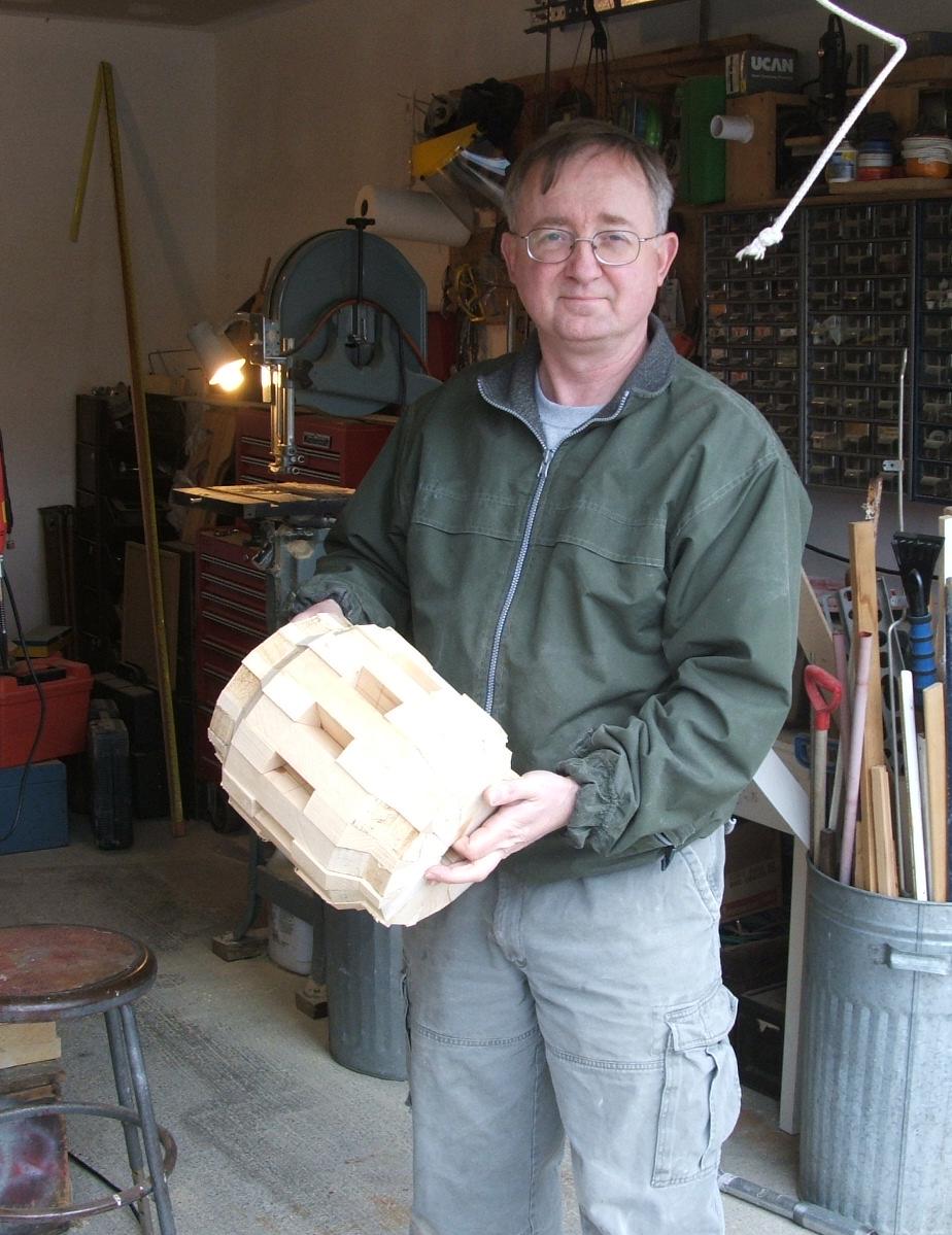
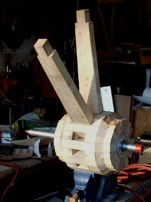
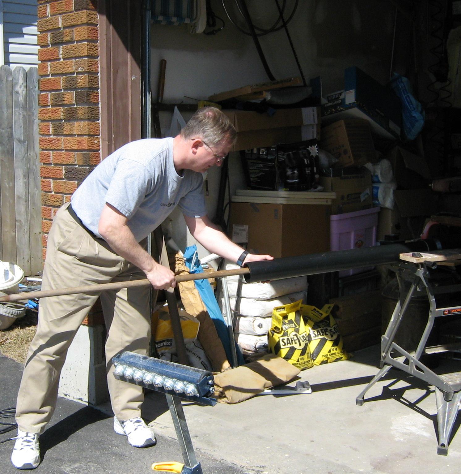
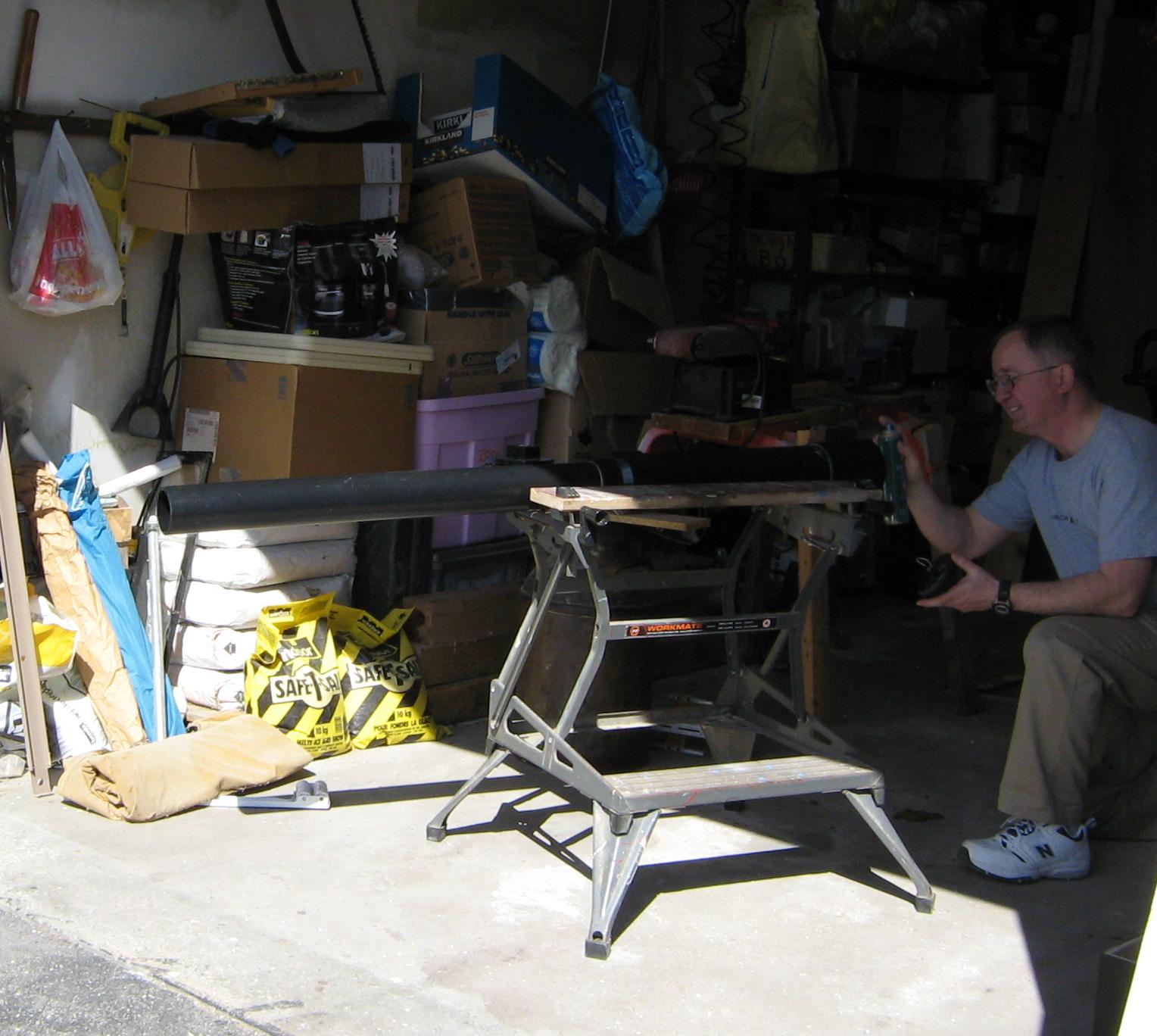
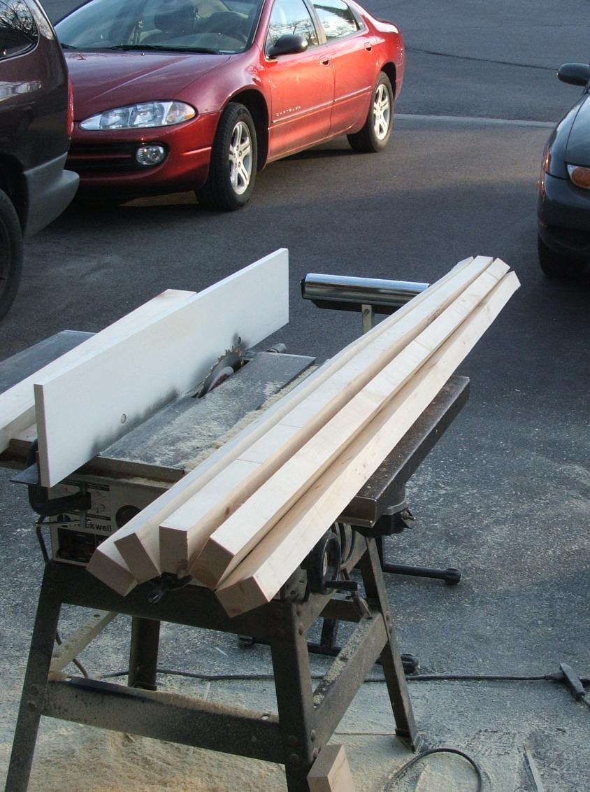
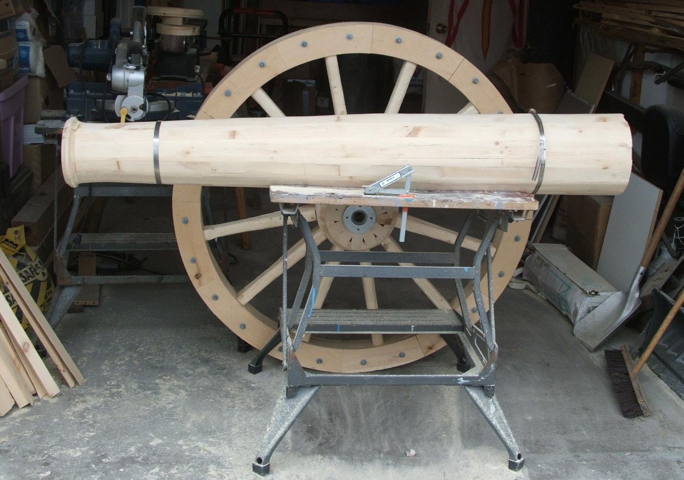
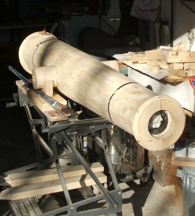
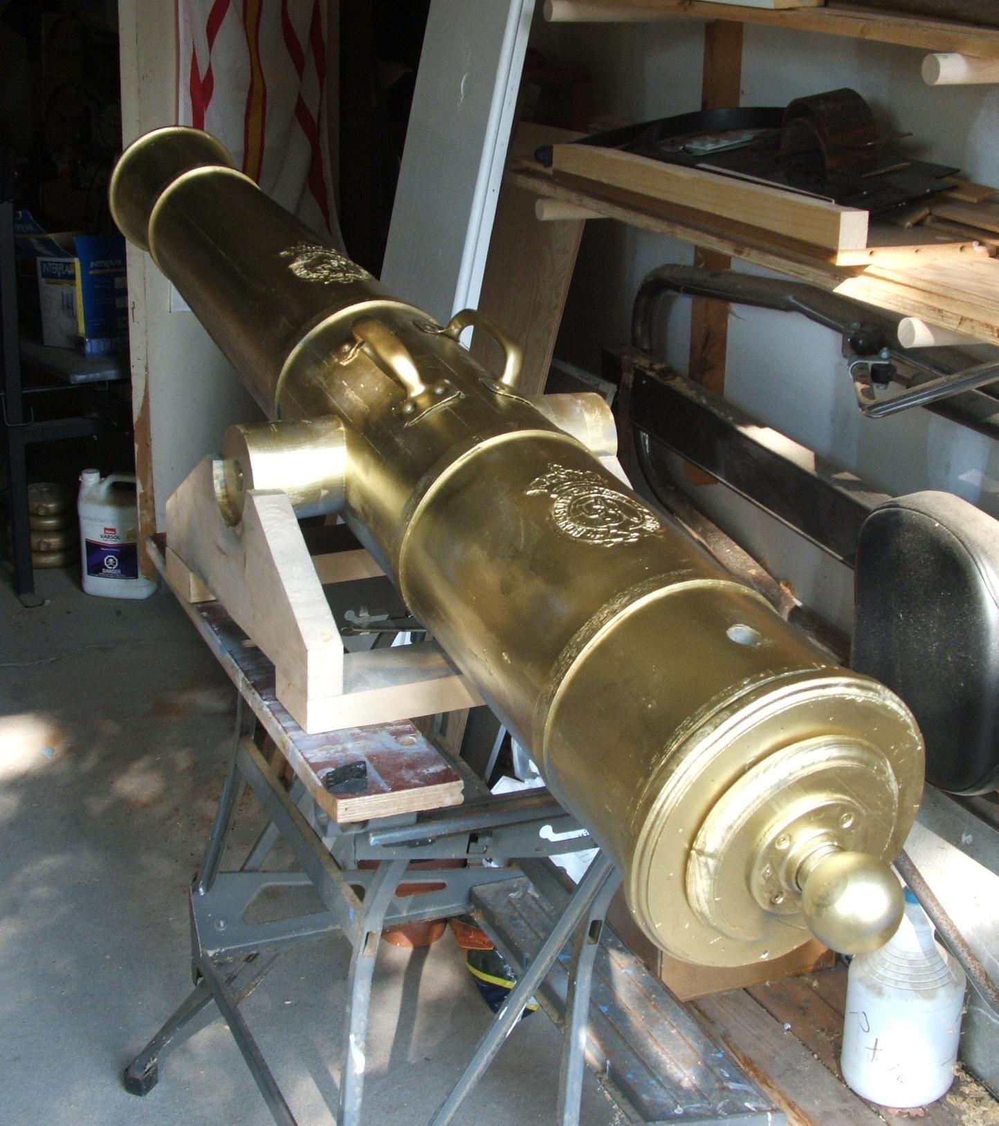
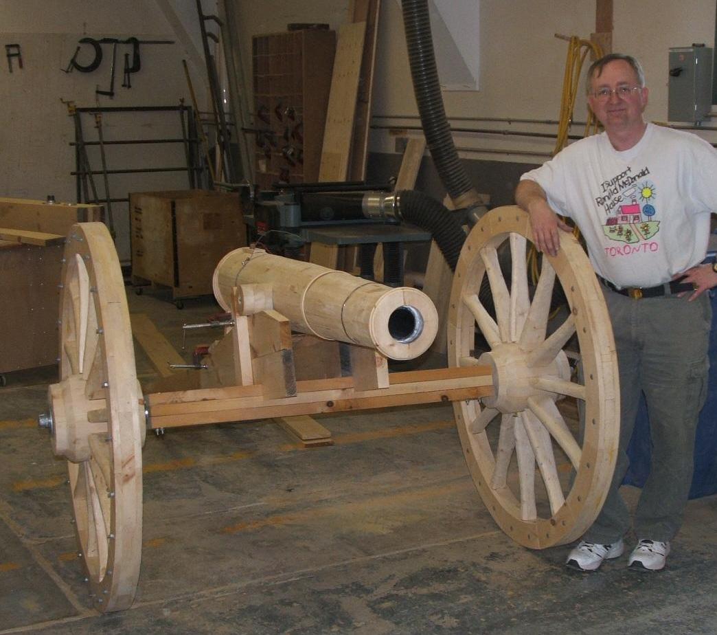
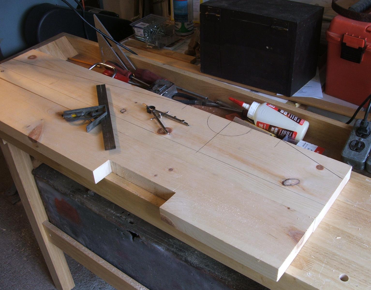
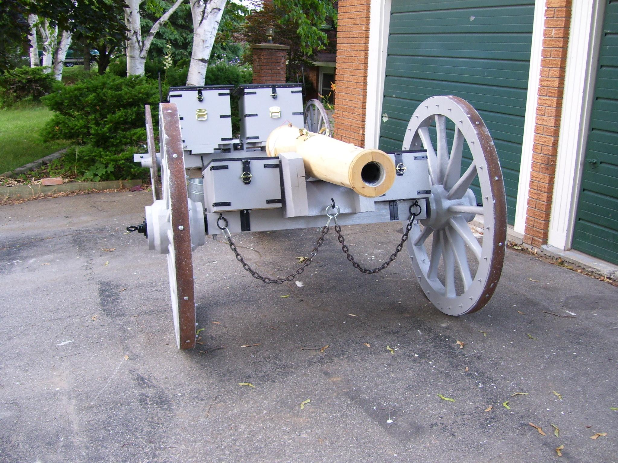
Step 3: Build the Gun
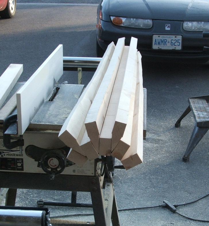
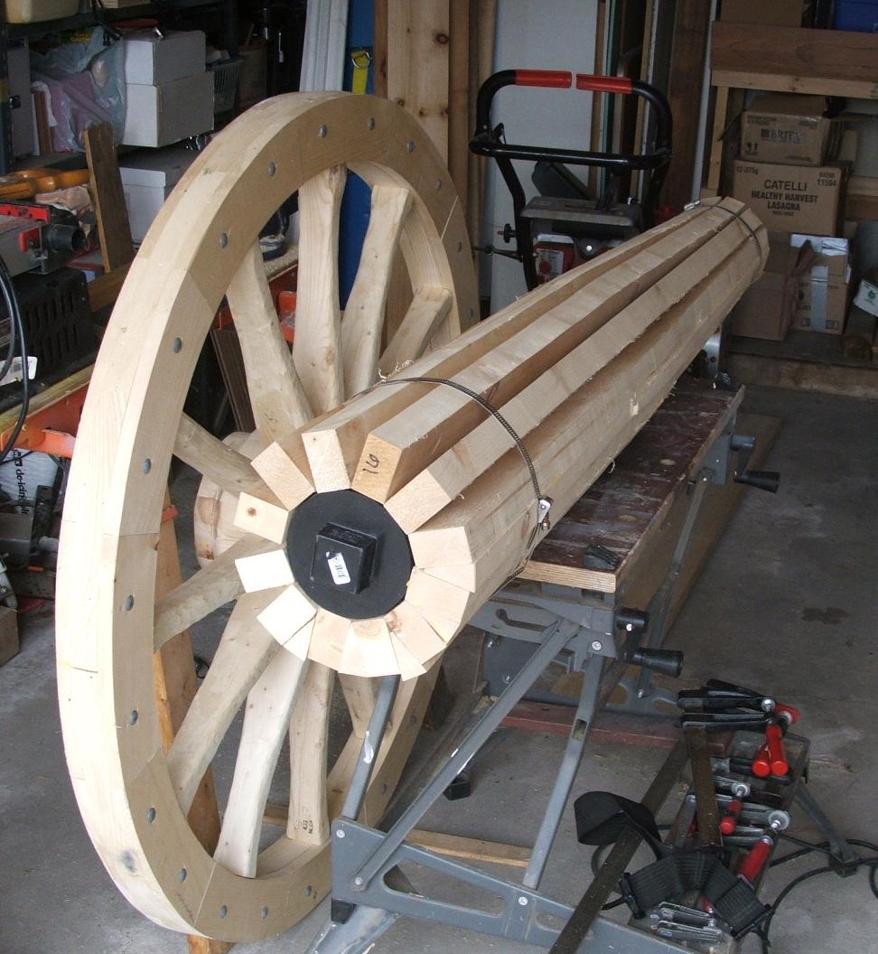
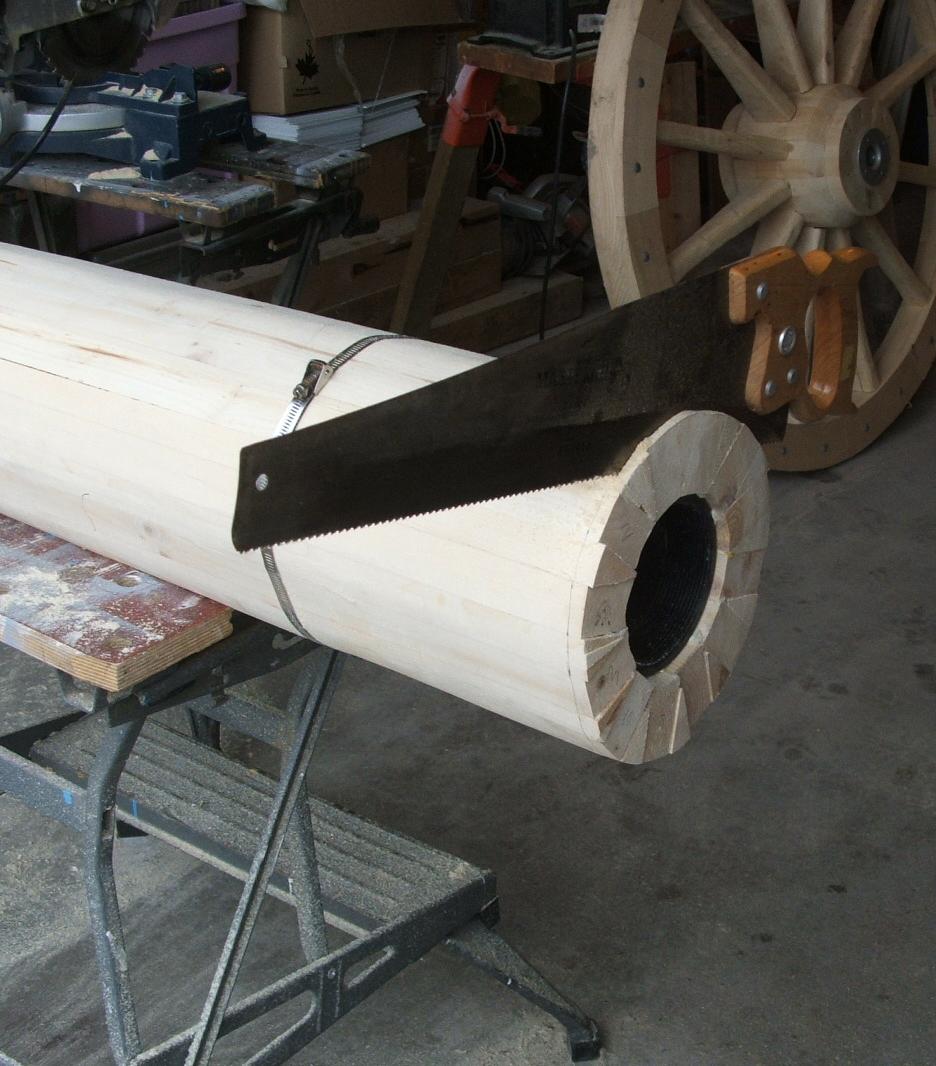
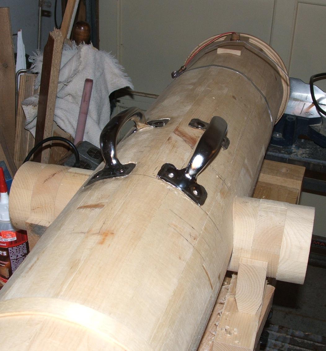
The cannon barrel is a wooden shell constructed from 30-degree sections and wedges similar to a wheel hub. The shell encloses an ABS 'potato' gun approximately 5' long, with chamber of 5” and a bore of 3 inches.
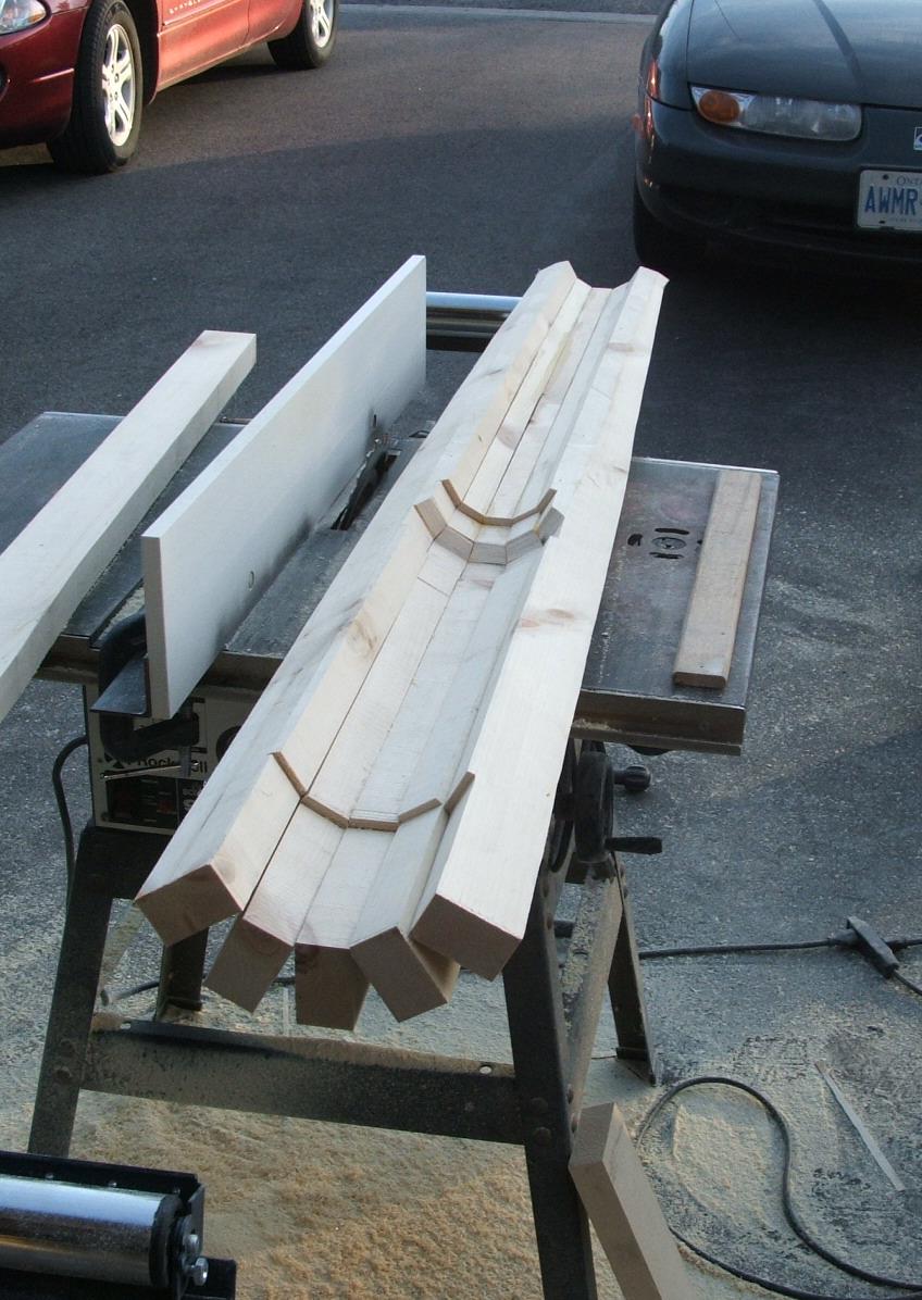
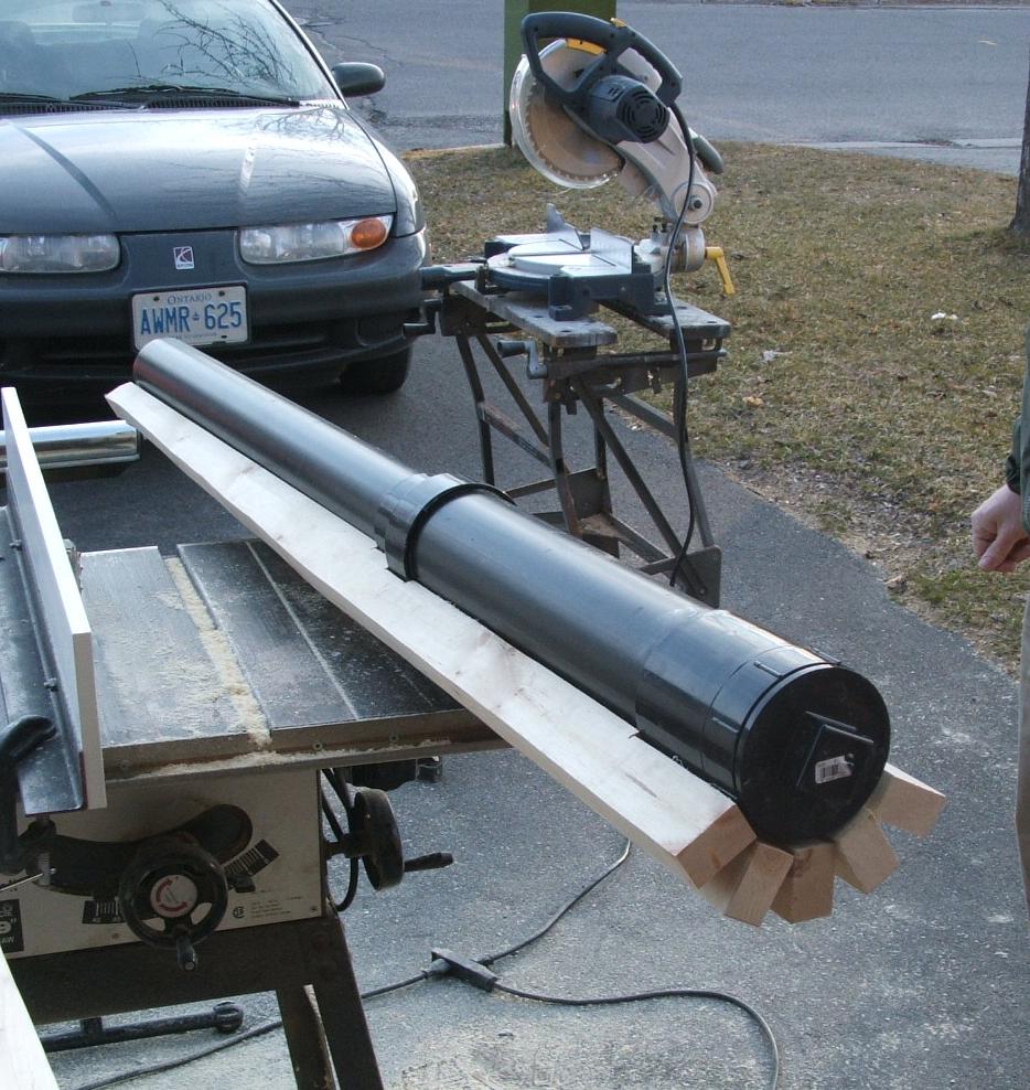
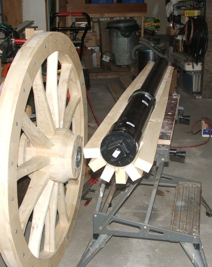
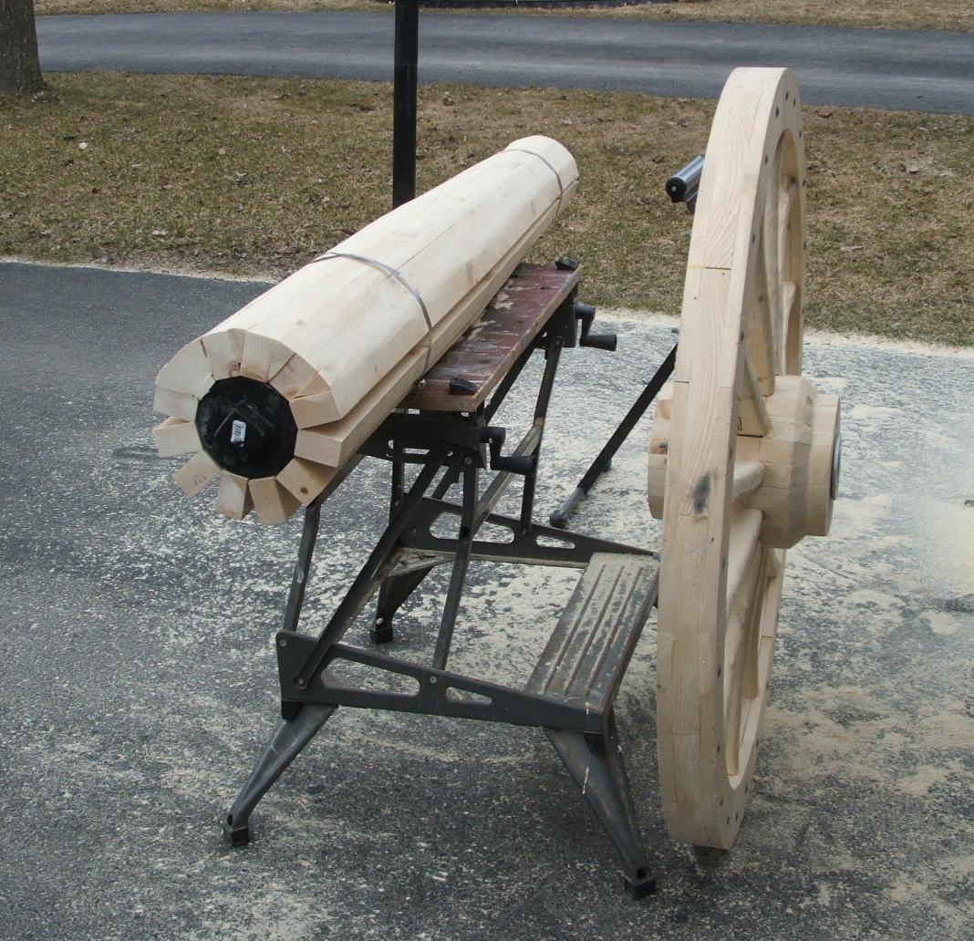
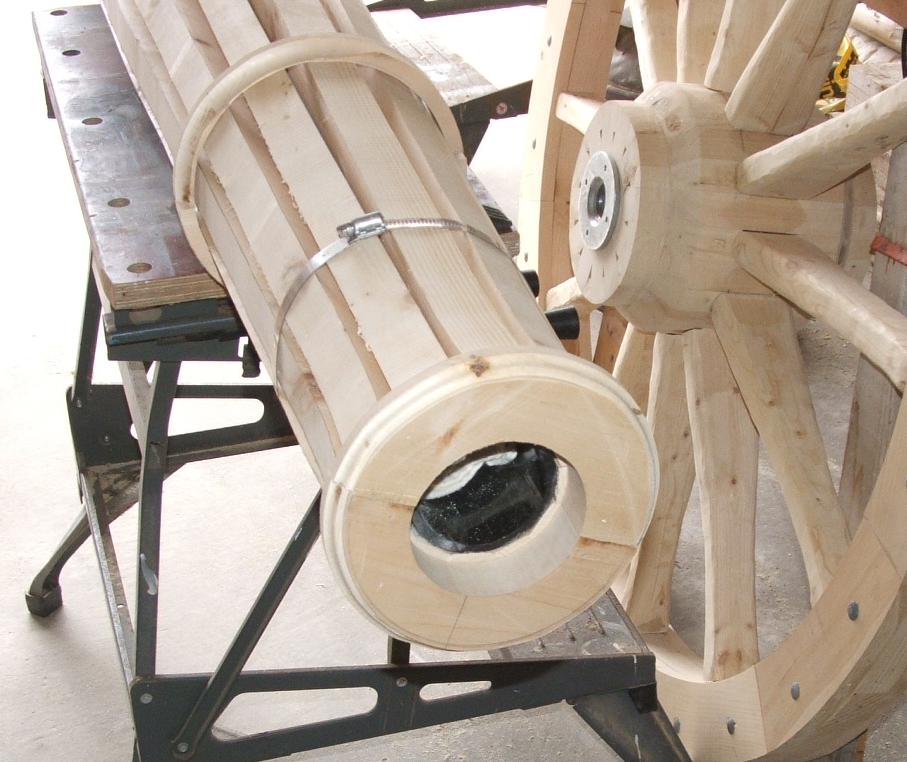
The union connecting the 5” chamber to the 3” bore is lined up with the trunnions. A piece of ¼” ready rod through the centre of the trunnions goes through the centre of the bore at the union. It is important that this rod is there to prevent any wadding from being rammed into the breach and jammed. This is extremely important as a jammed wad could cause the chamber to burst upon firing.
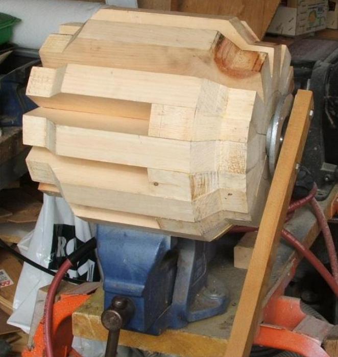
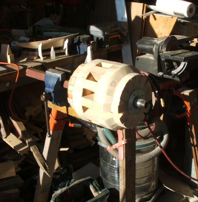
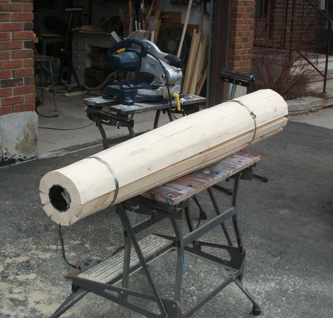
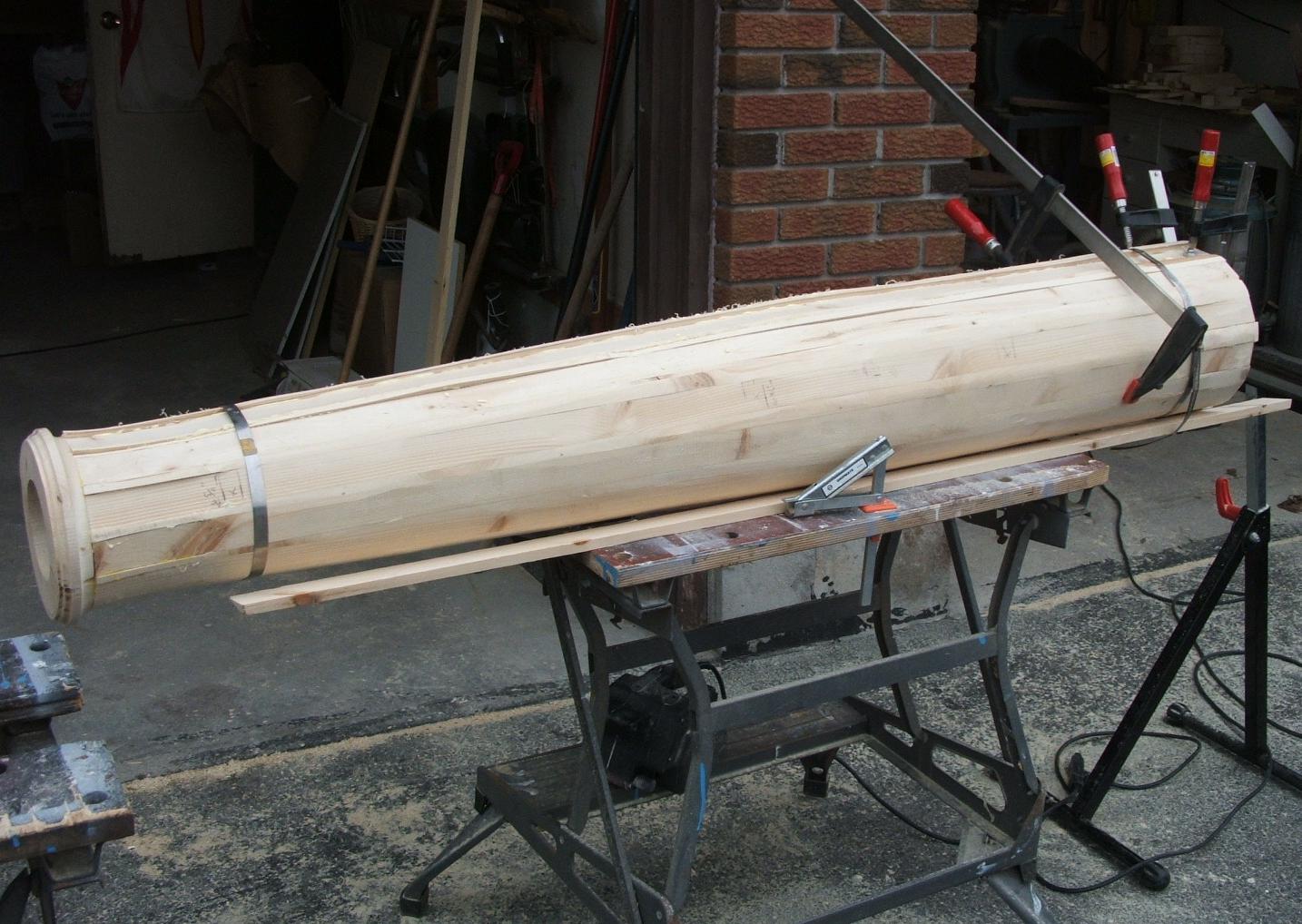
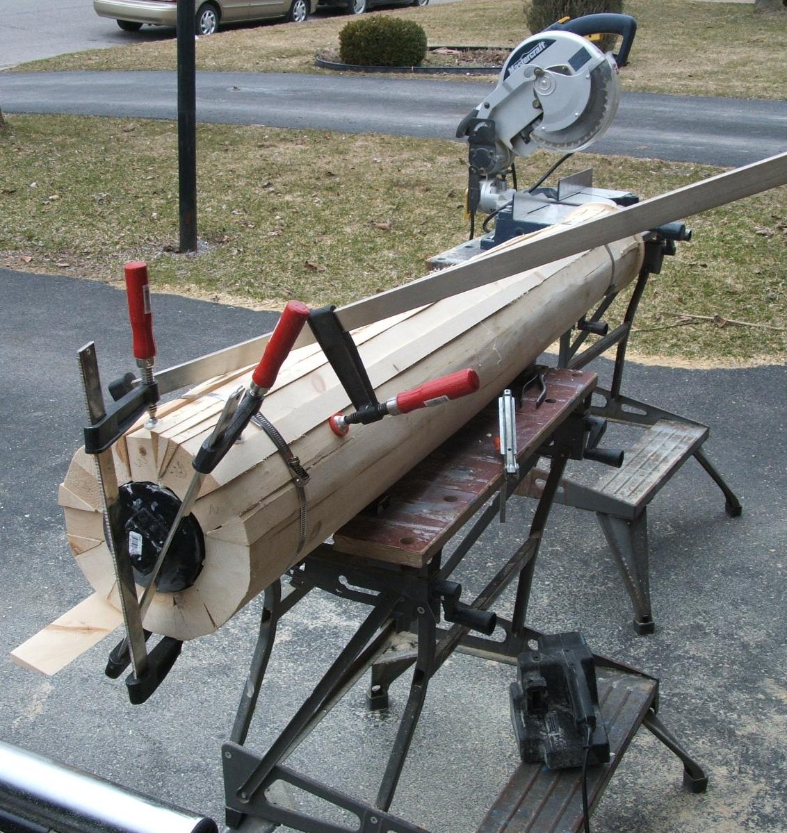
The wood sections are cut to the shape the ABS gun on the inside, and to the shape of the 9-pounder brass cannon on the outside. Additional wedge sections fill in the gaps. The barrel assembly is then sanded round.
When complete, the whole barrel assembly will be outfitted with dolphins, a removable breach, trunnions, and the ciphers, and finished in the colour of bright brass.
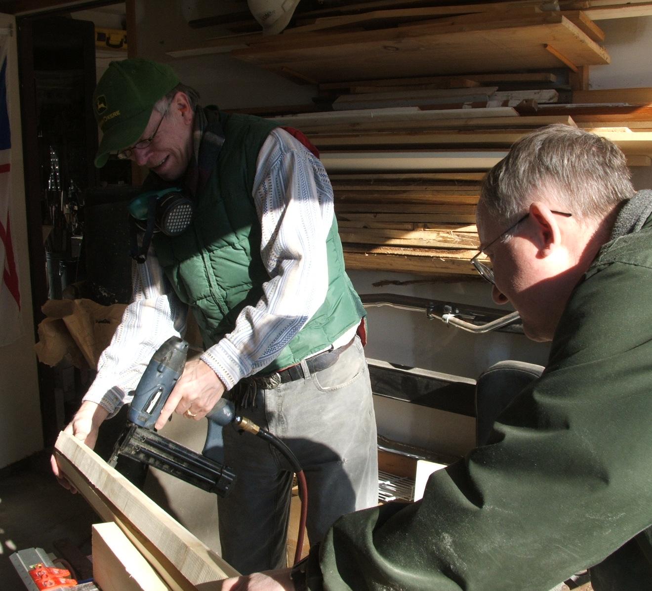
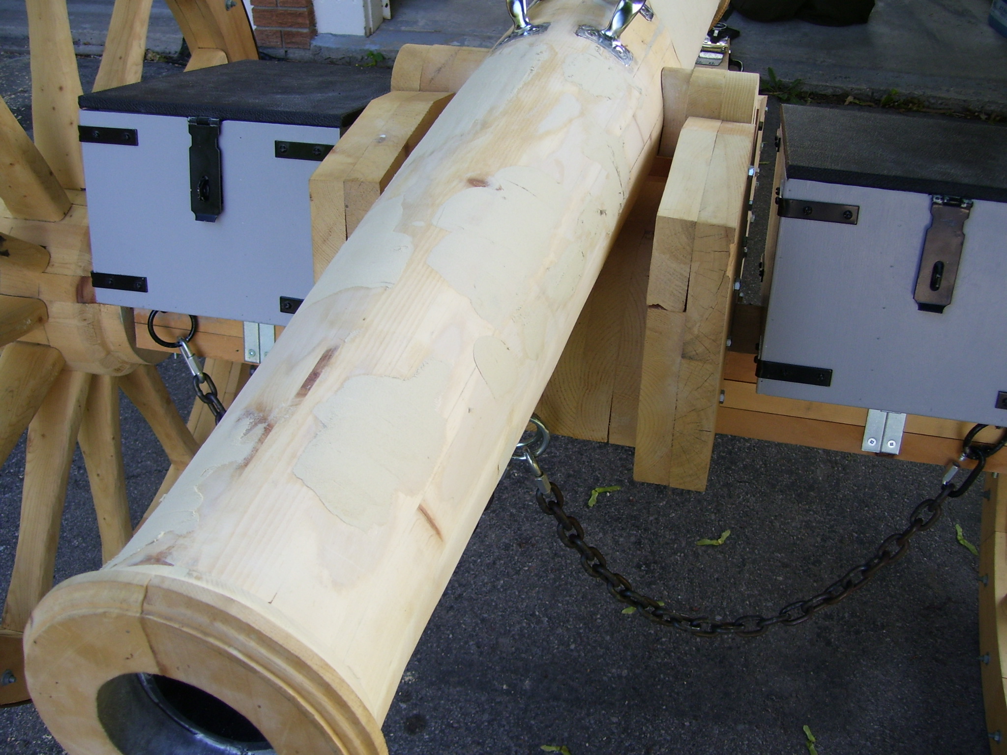
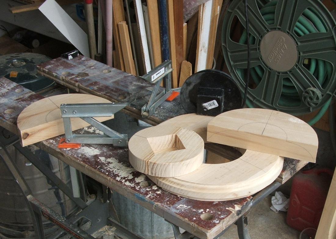
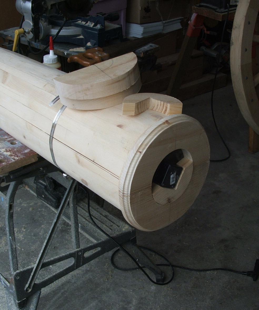
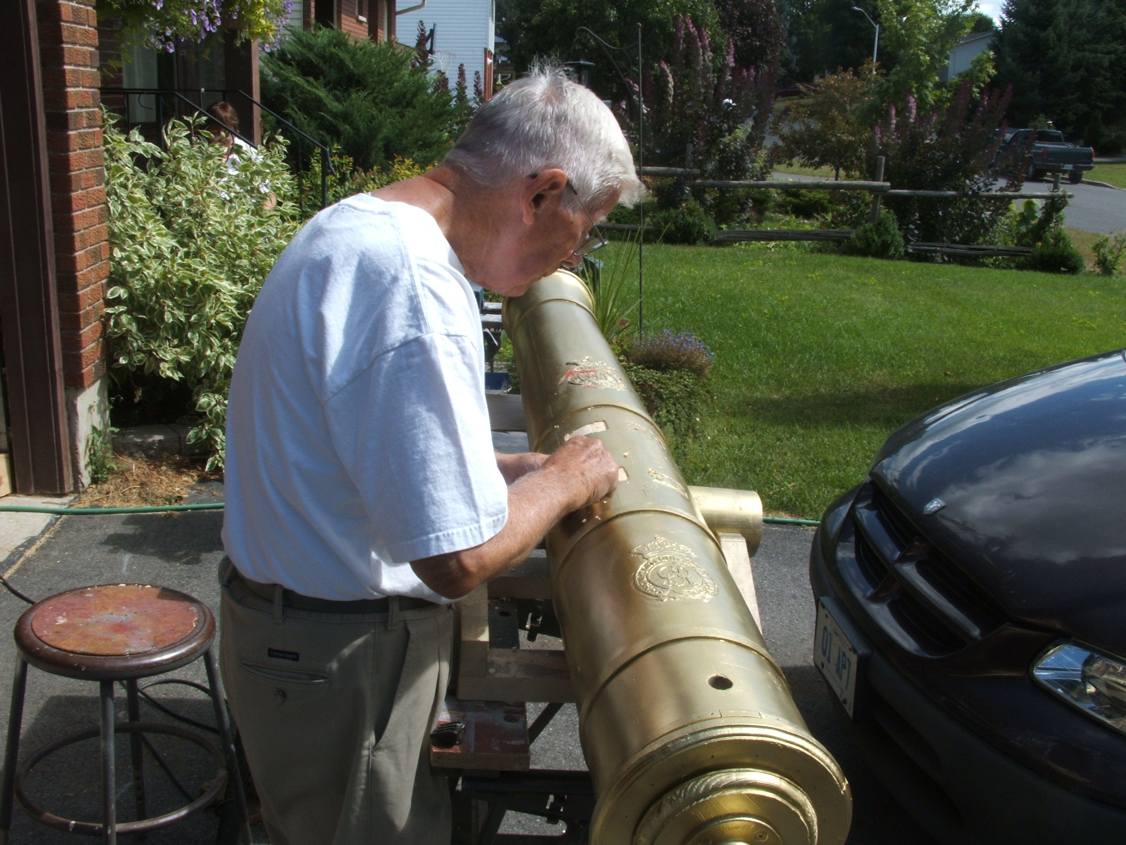
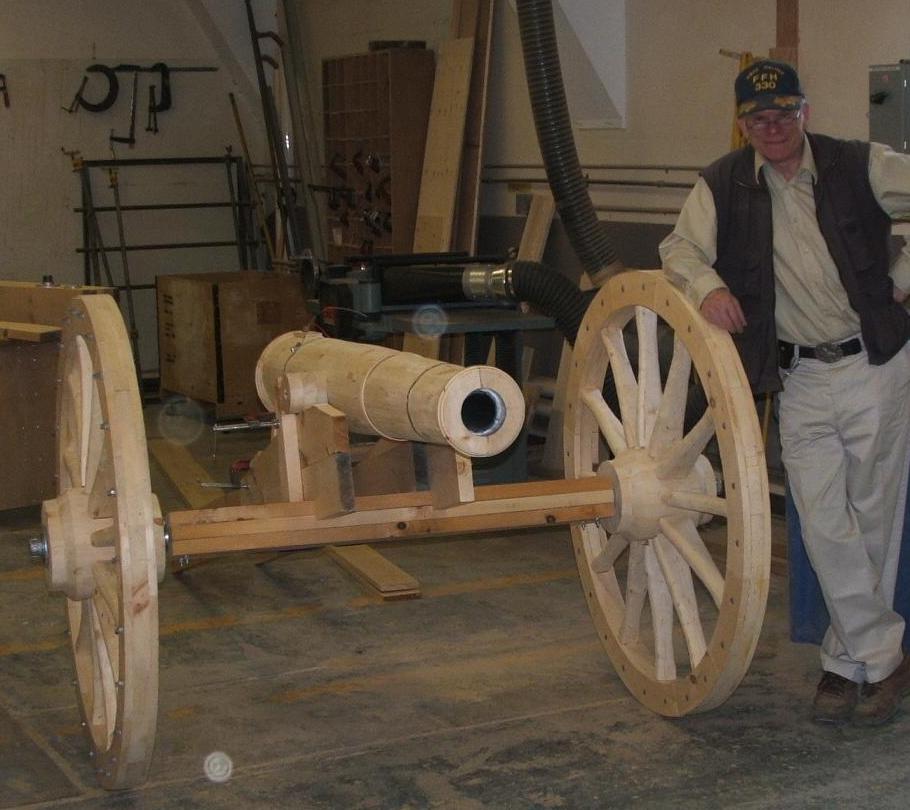
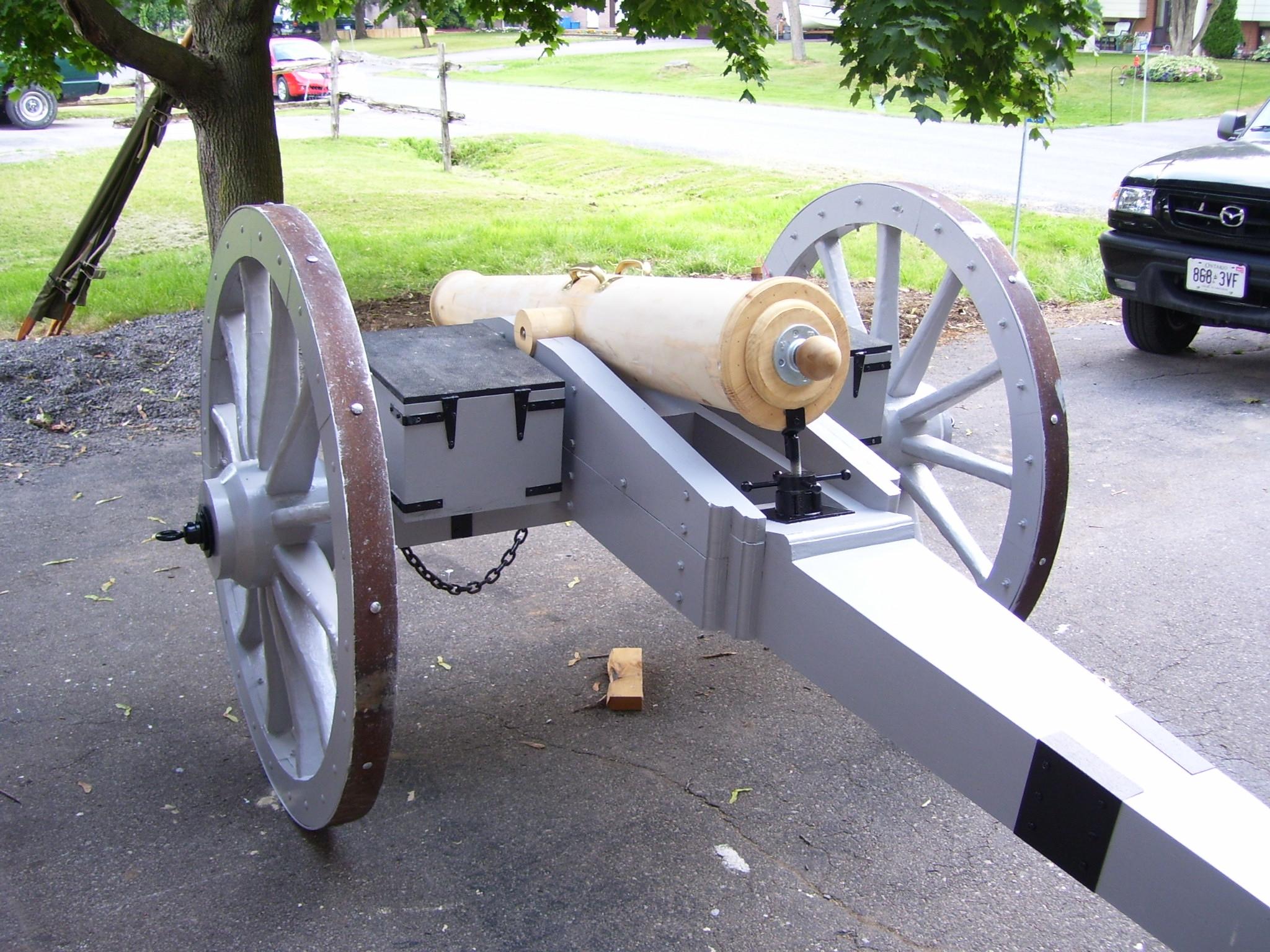
Step 4: Outfit the Gun
The gun is furnished with the addition of trunnions, muzzle and breech caps, reinforcement bands and an ignition device.
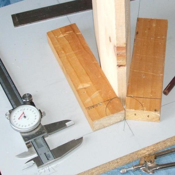
The trunnions are each constructed from 3 cut-outs of 2”x6” plank and secured to the gun with threaded rod, at the breach-to-barrel union. This prevents ramming the wadding into the breech, where it could jam and present a hazard upon firing.

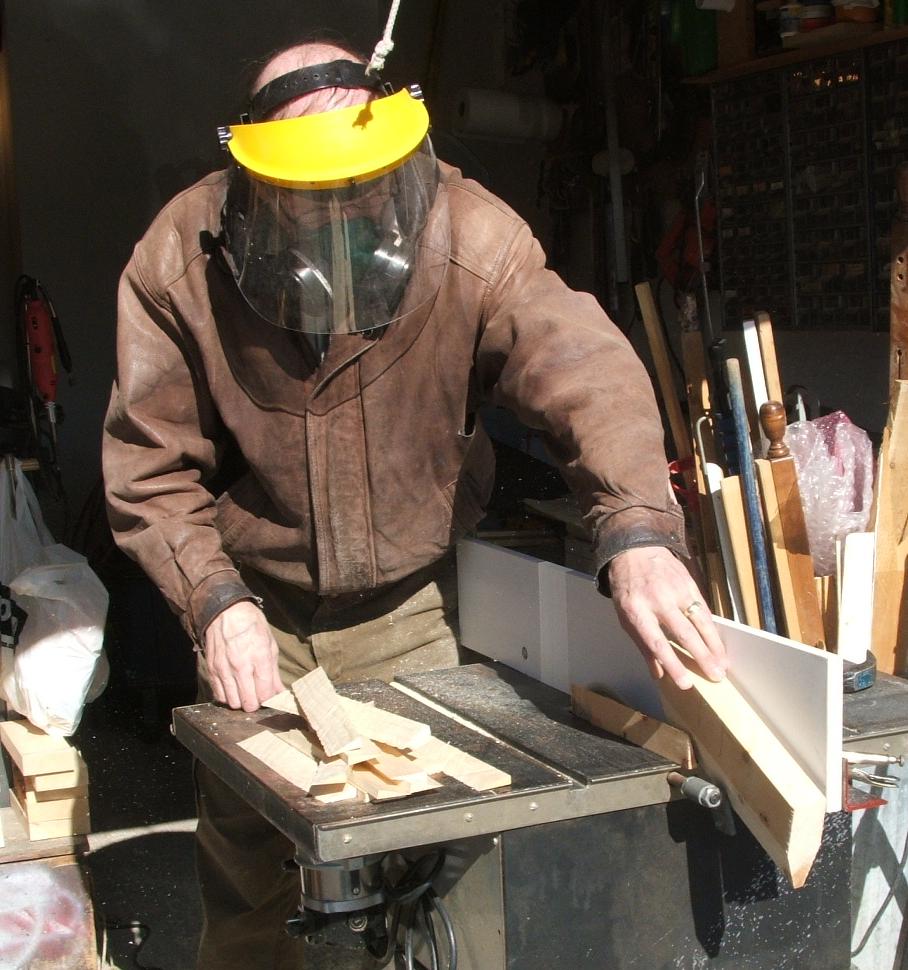
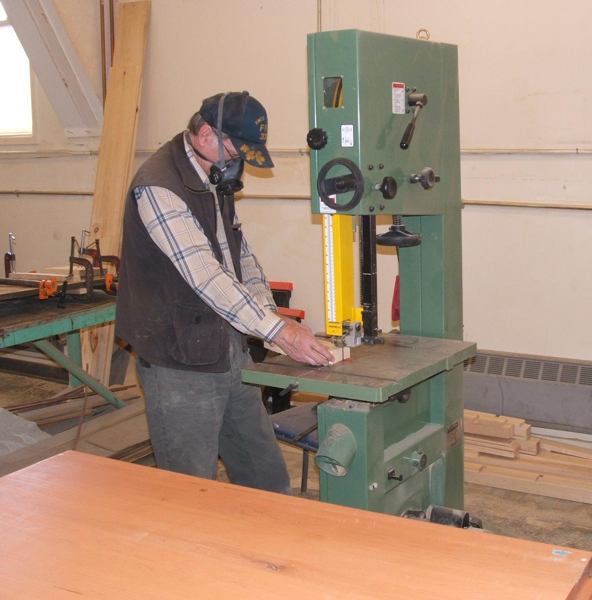
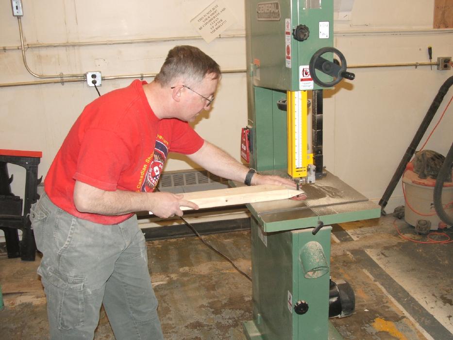
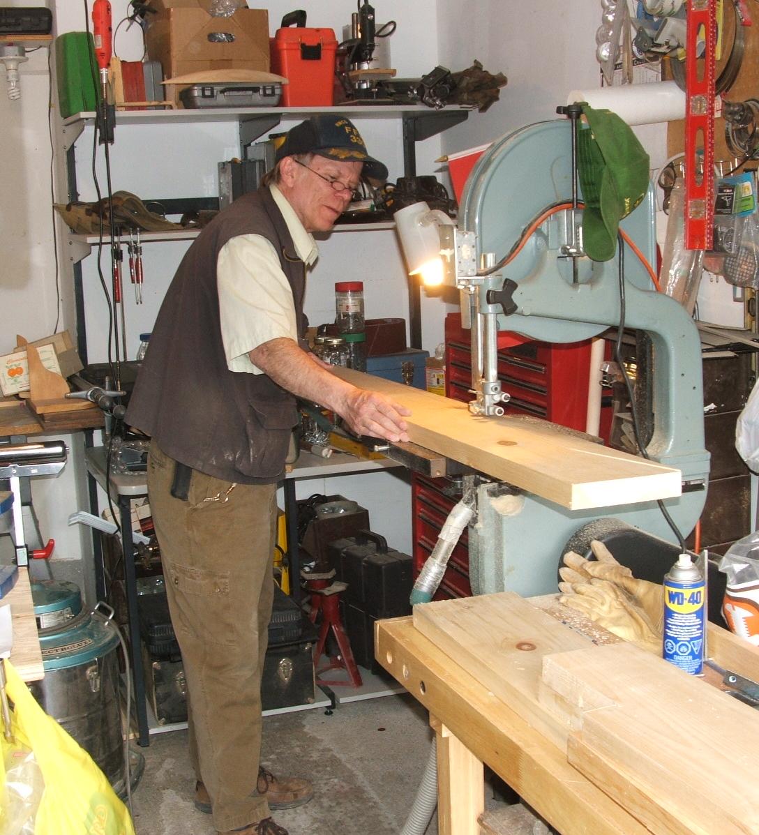
The breach and muzzle end caps are made from 2”x6” plank cut with a band saw, routed and sanded.
The breach cap has an additional plate, cut from 2”x6” plank, routed and sanded. To this was added a 1.25” steel pipe flange, a short nipple and an end cap. The 1.25” steel end cap was sanded round and fastened inside a 3” wood ball, which was bored out. The flange was covered with a resin based body filler and contoured into the ball. This assembly was attached to the cap of the 5” APS chamber, so the breach assembly could be screwed on to the chamber.
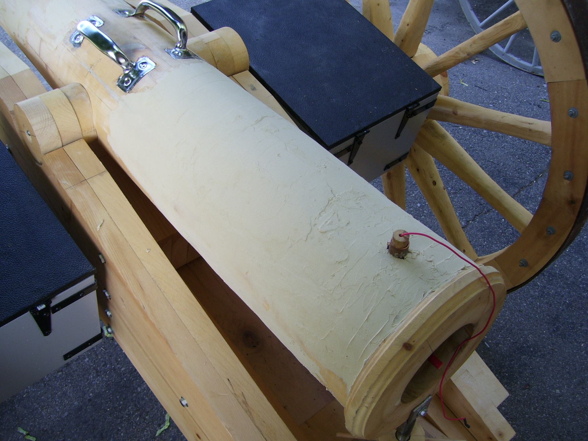
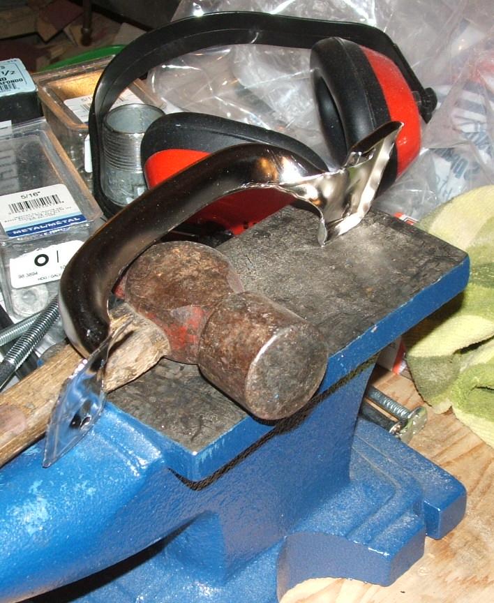
The dolphins were a pair of large gate handles with the ends flattened and countersunk into the barrel.
The ignition device was made from a barbeque lighter, fixed to an additional 5” APS chamber cam, and used when the gun was in action. Attempts to fix a sparkplug and operate with a remote firing ‘stick’ failed due to fouling of the sparkplug when charging the chamber with the hairspray/deodorant fuel. Having the ignition device as a separate breach unit allows spares to be carried, which may prove useful in the field.
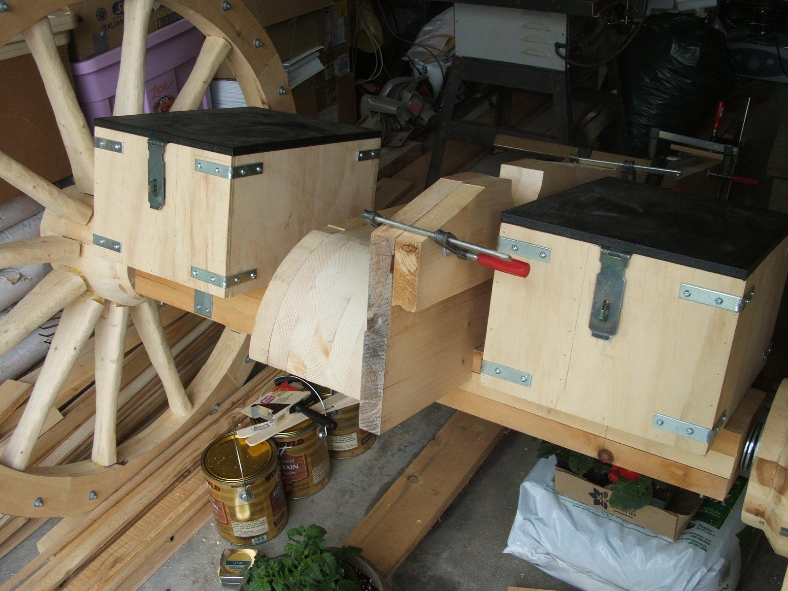
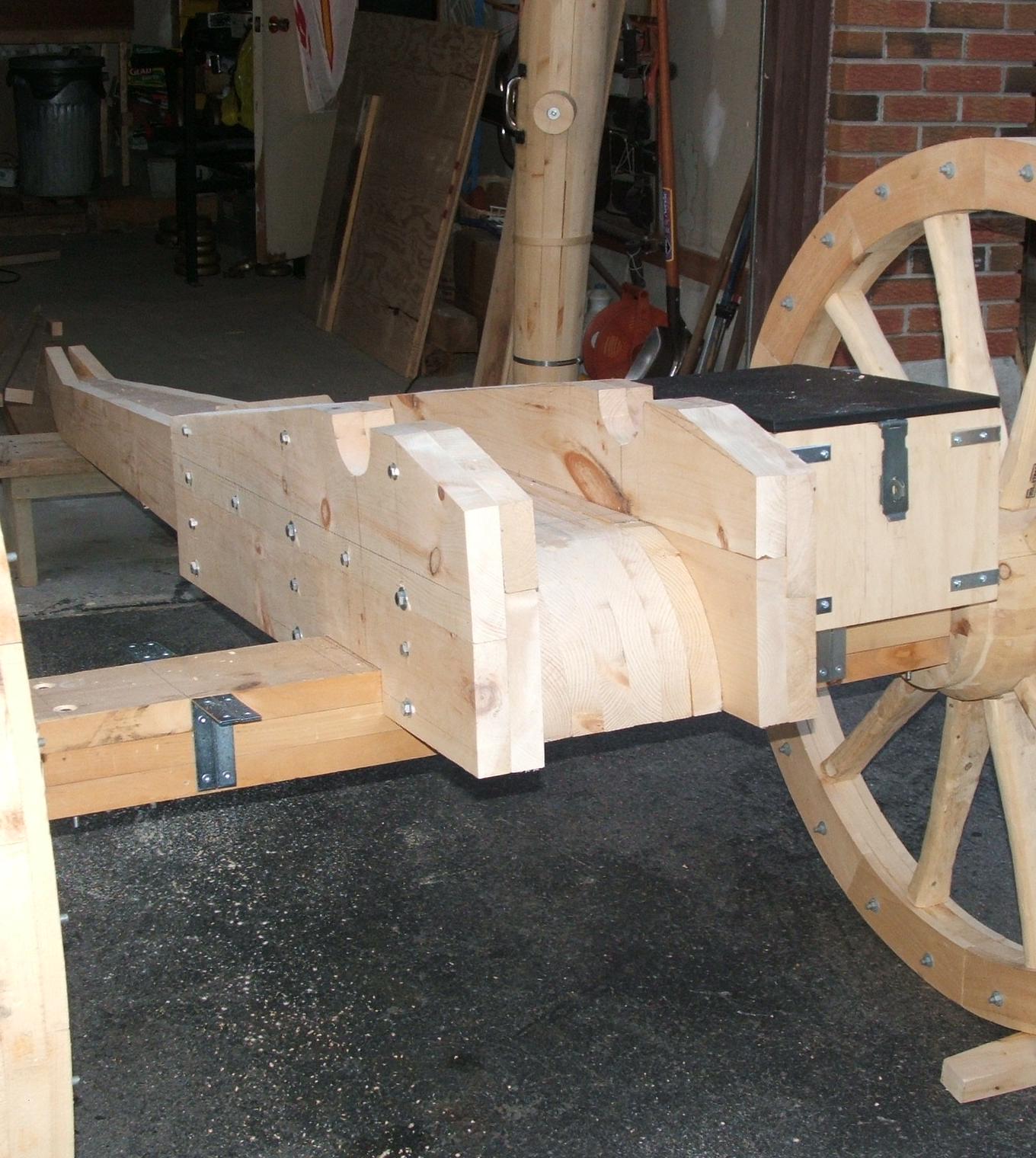
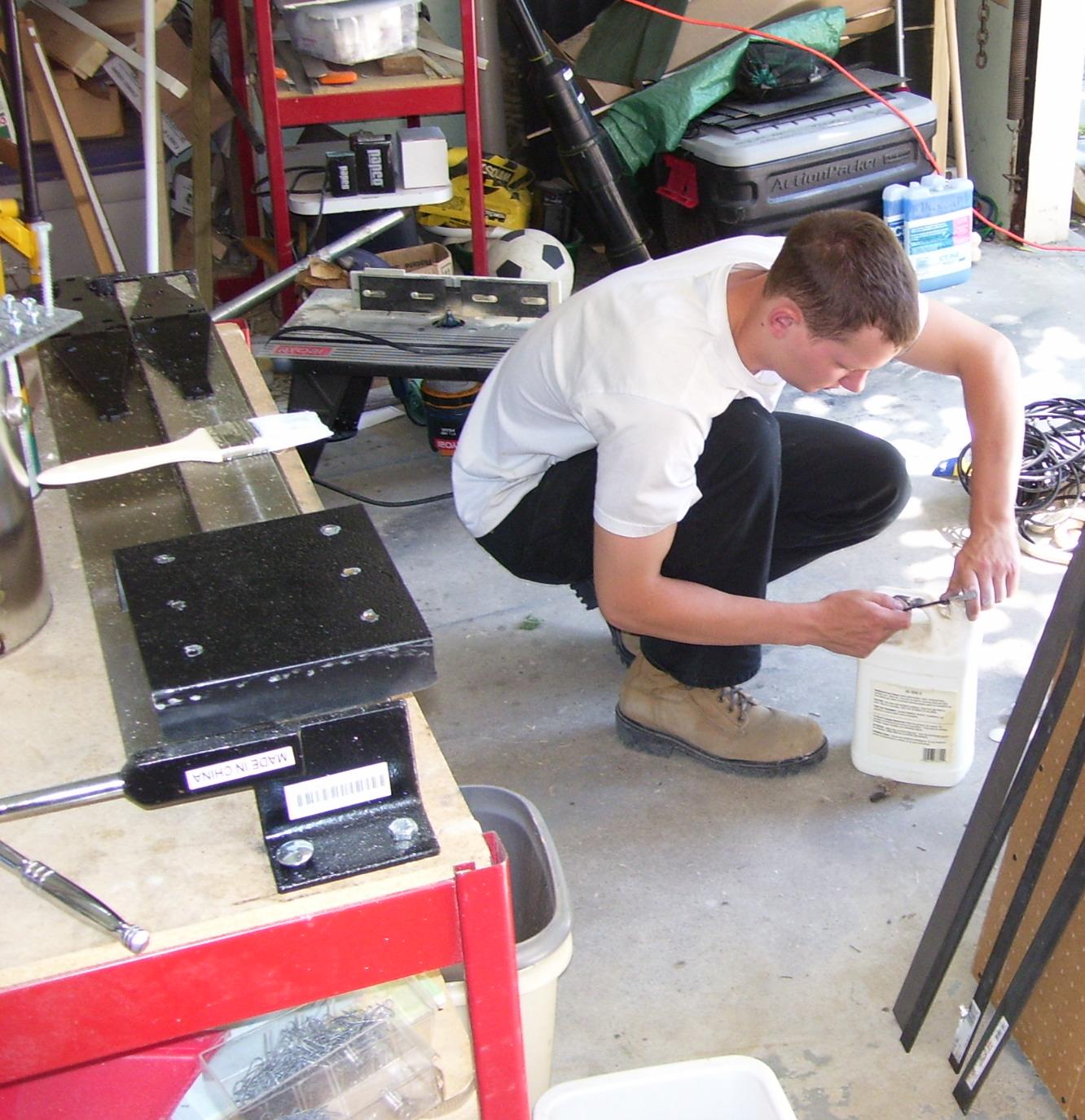
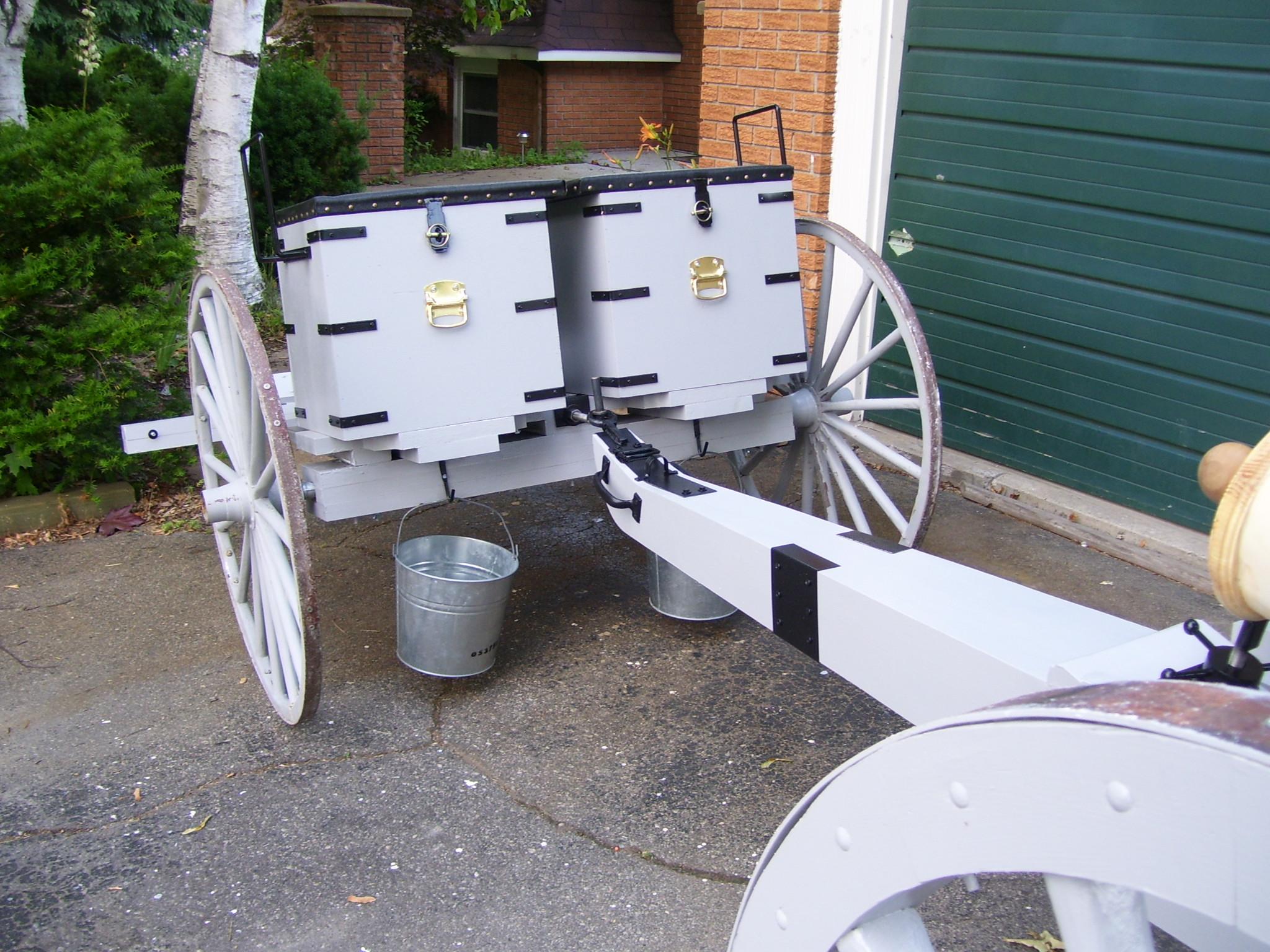
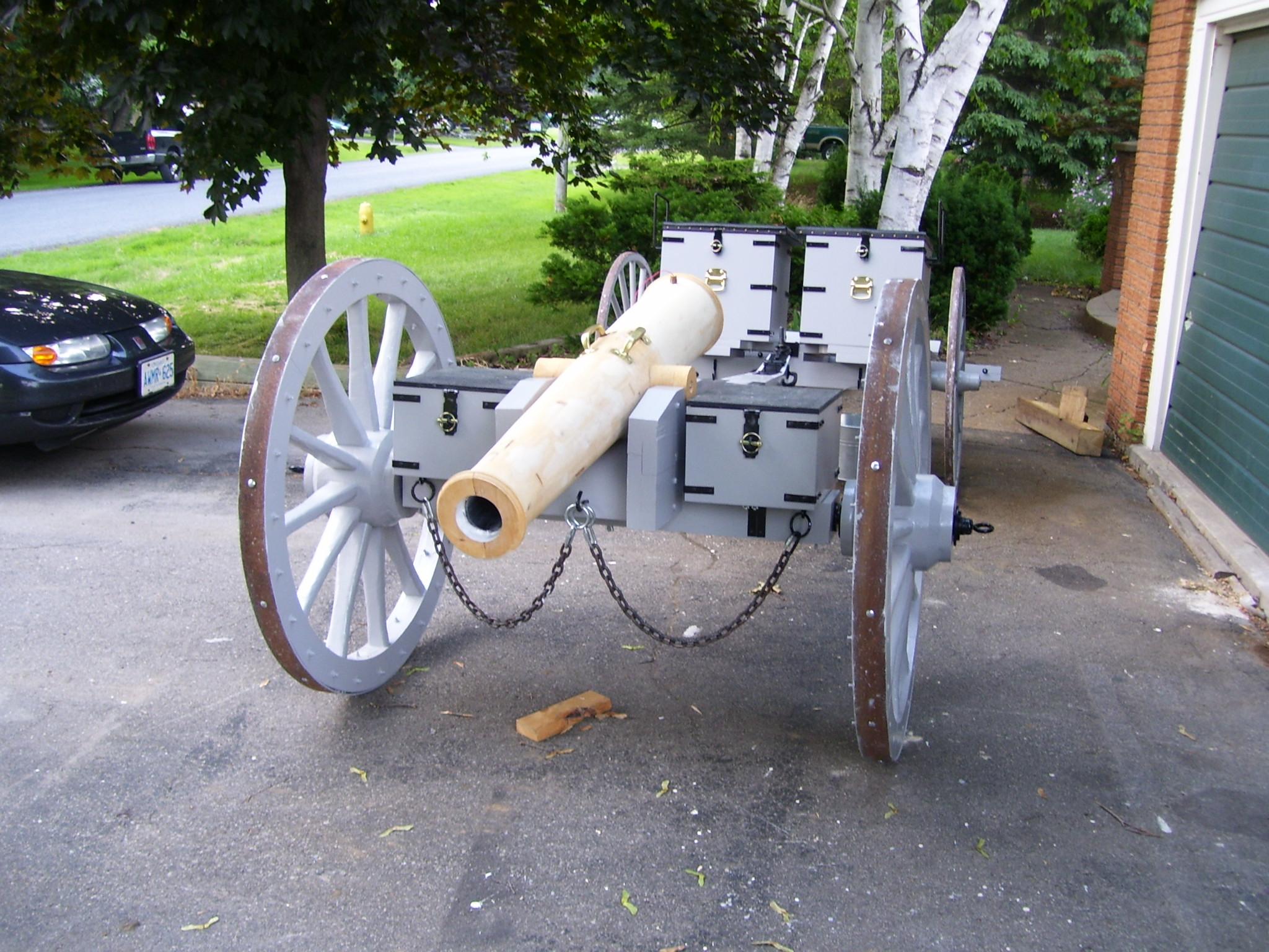
Step 5: Build the ammunition boxes
The ammo boxes are fabricated from ½” plywood, with provision for 8 x 4” cannon balls and accessories in each box.
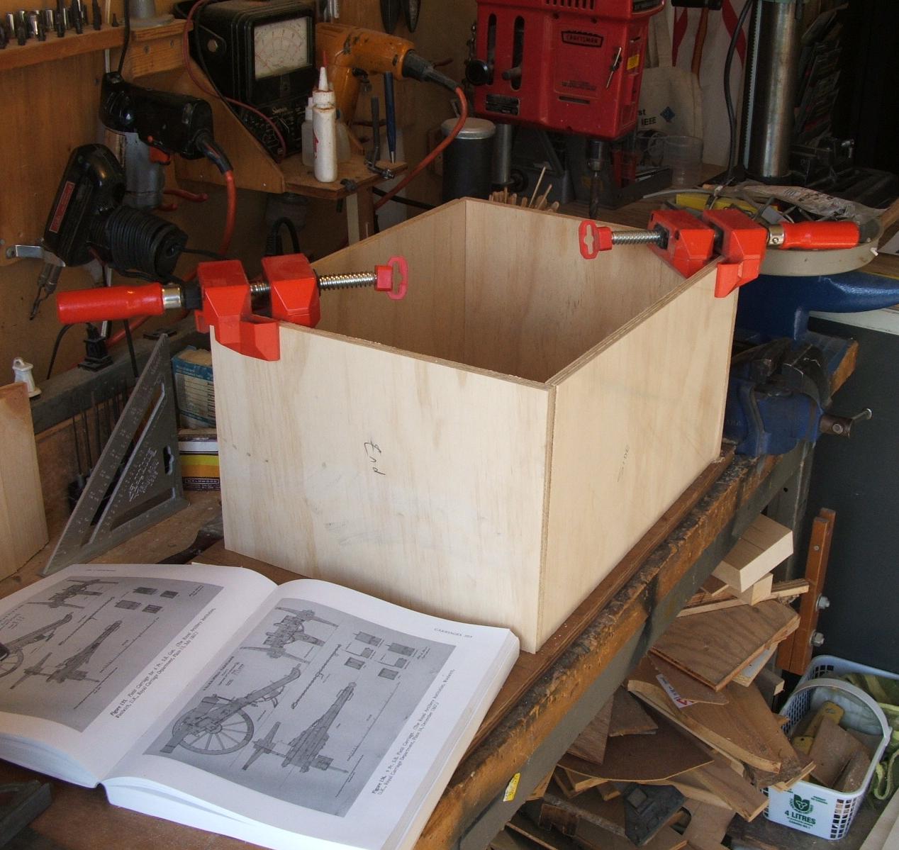
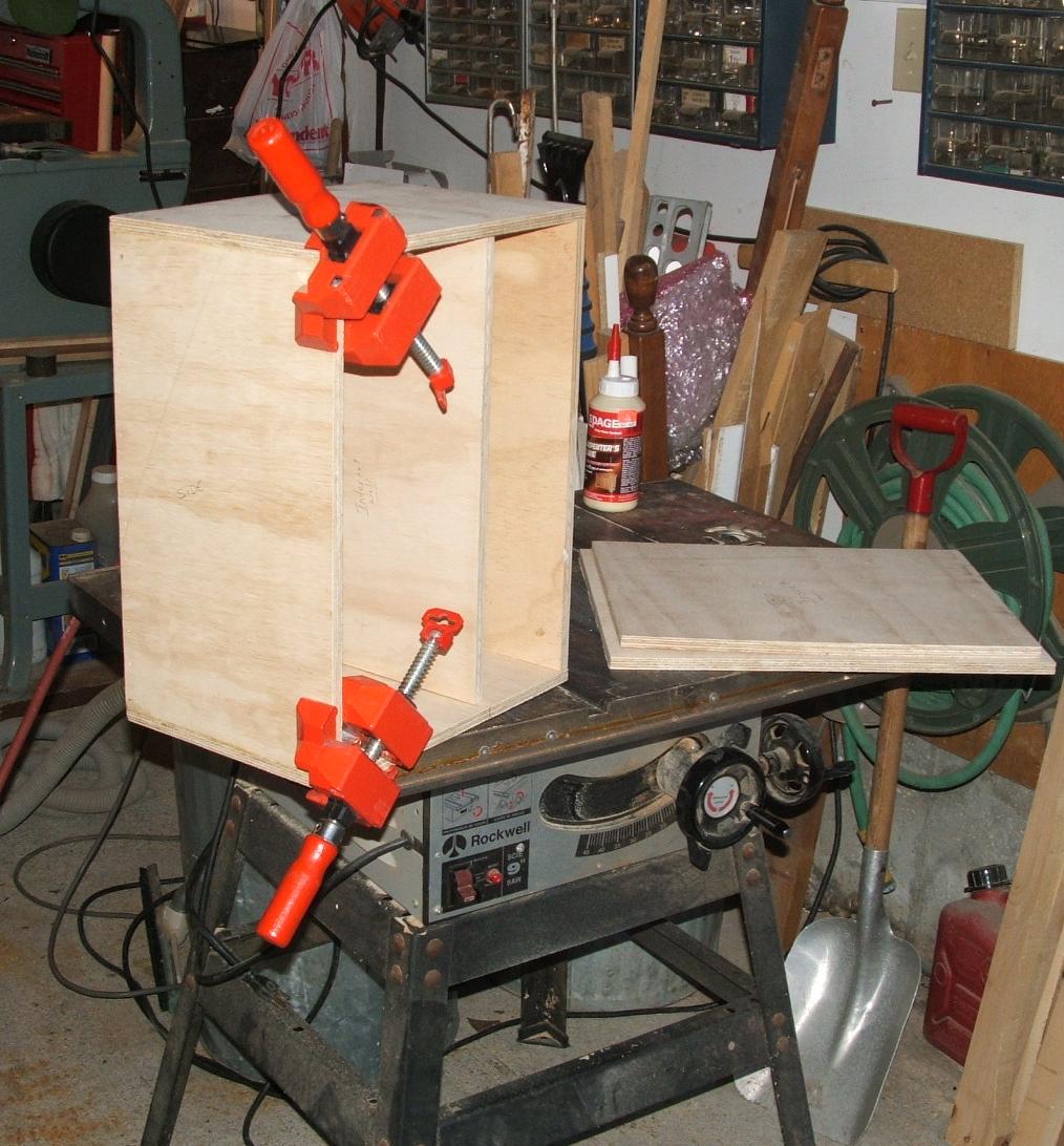
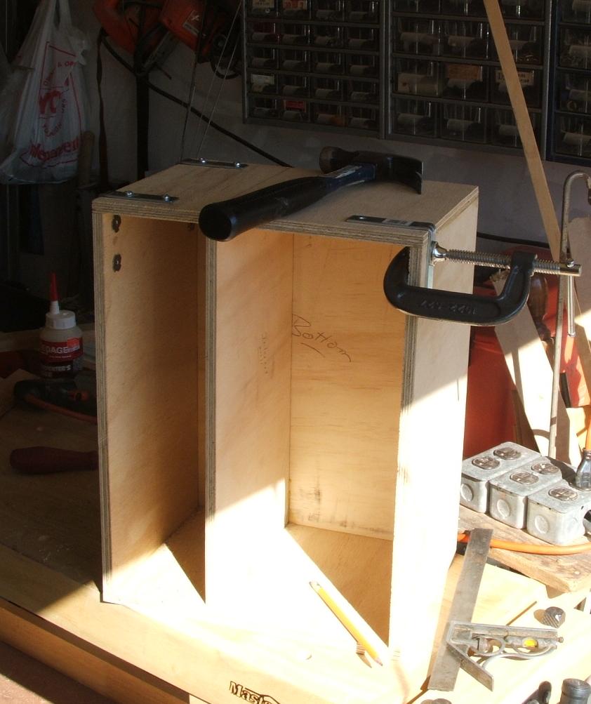
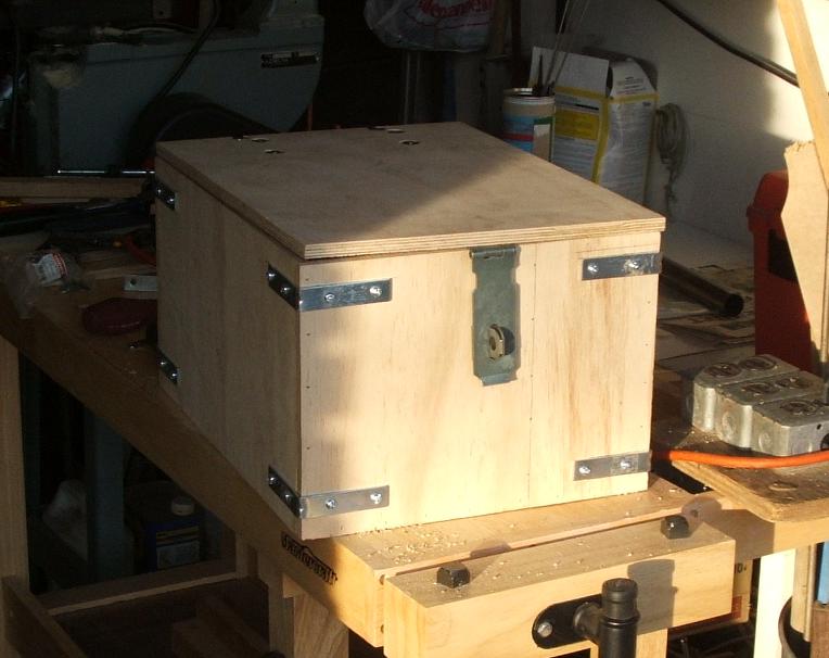

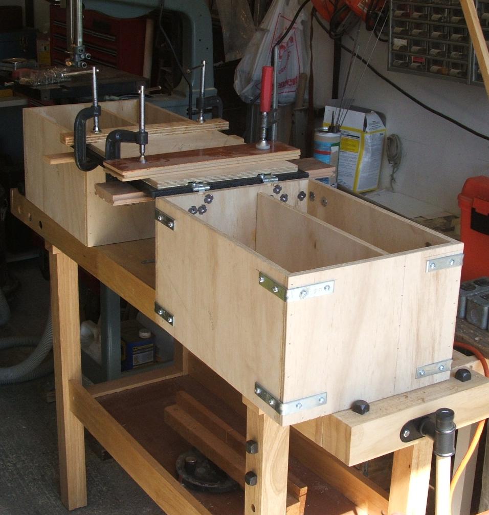
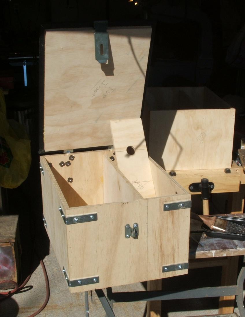
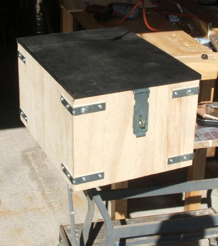
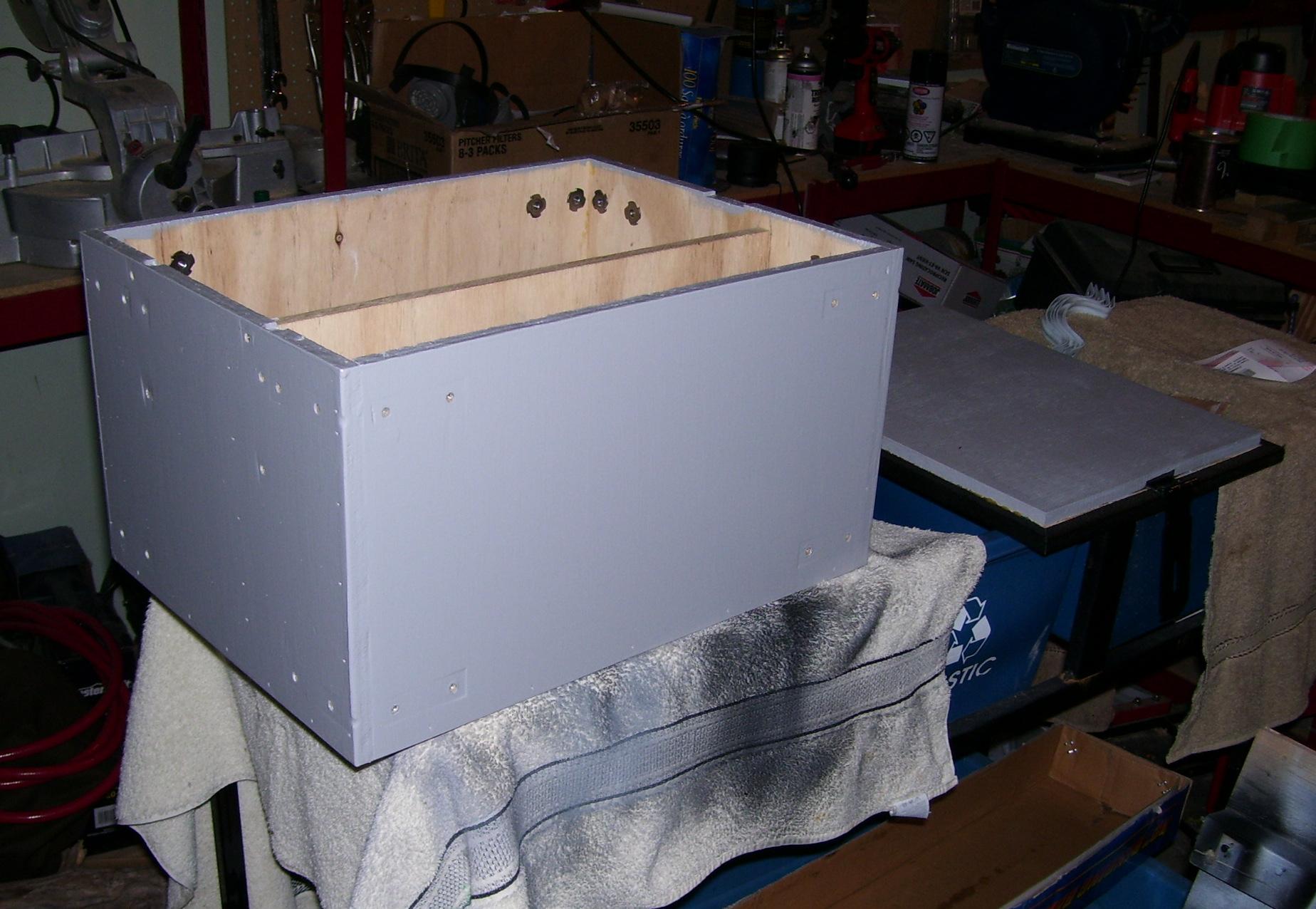
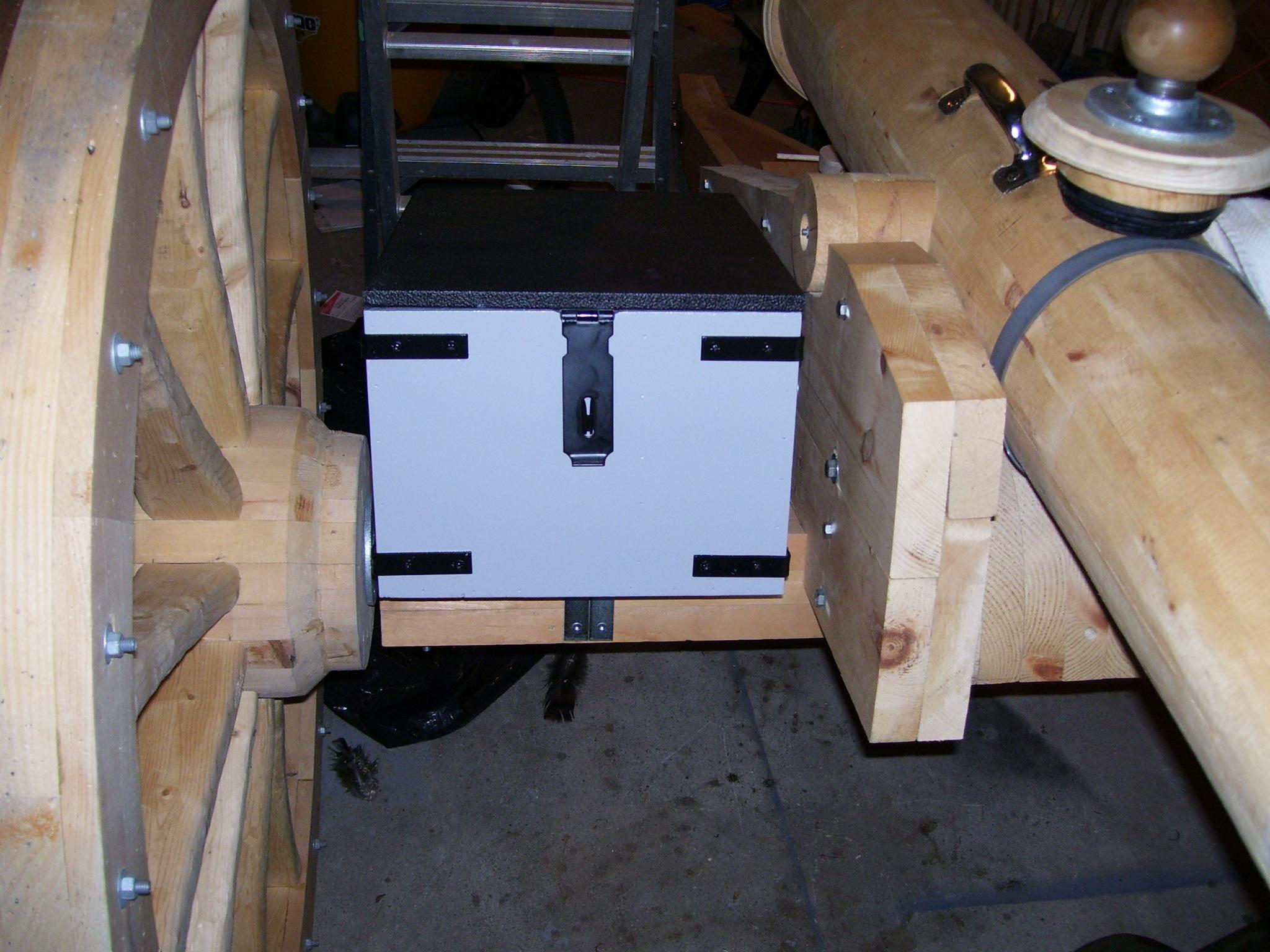
The box has a hinged Lid, covered with a leatherette material, and equipped with a latch. The box is reinforced with L-brackets and is bolted to the carriage axletree using angle brackets formed from 1/8” flat steel.
The livery is artillery grey with black hardware.
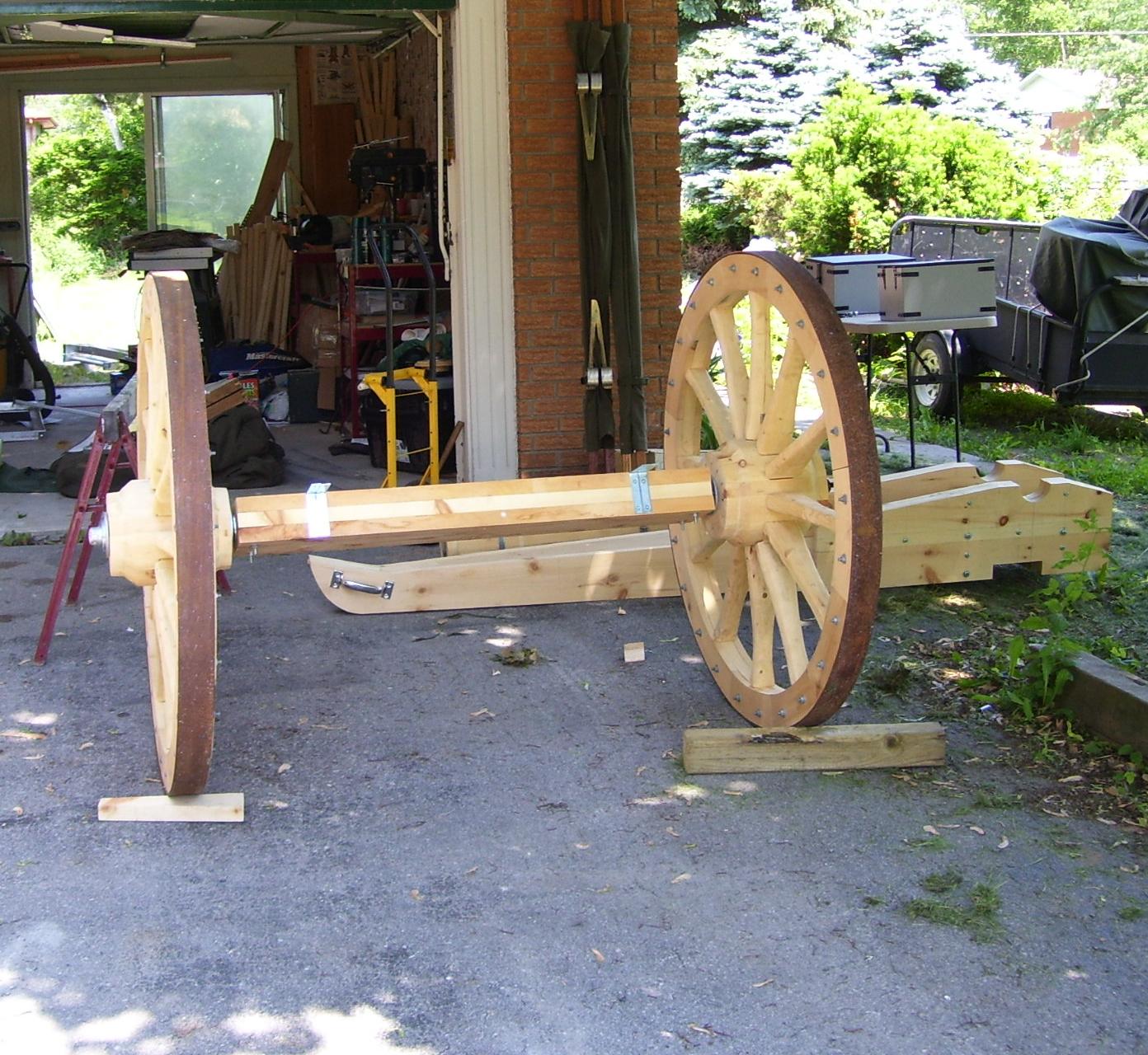
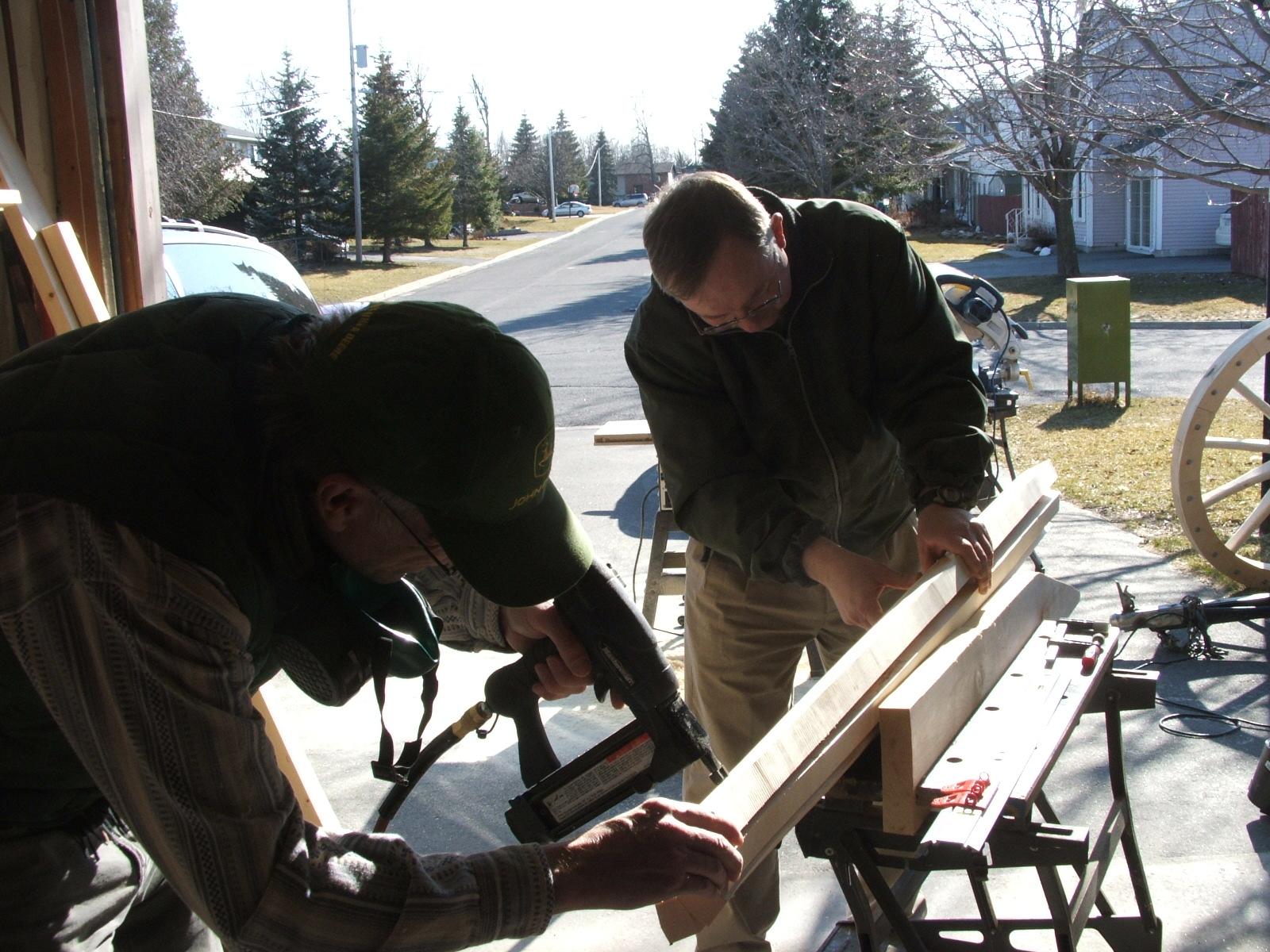
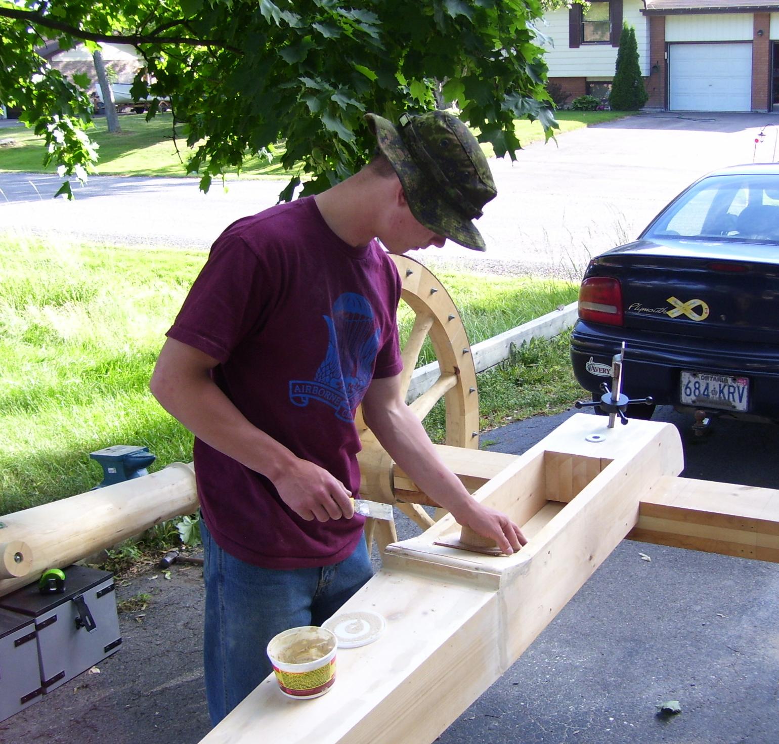
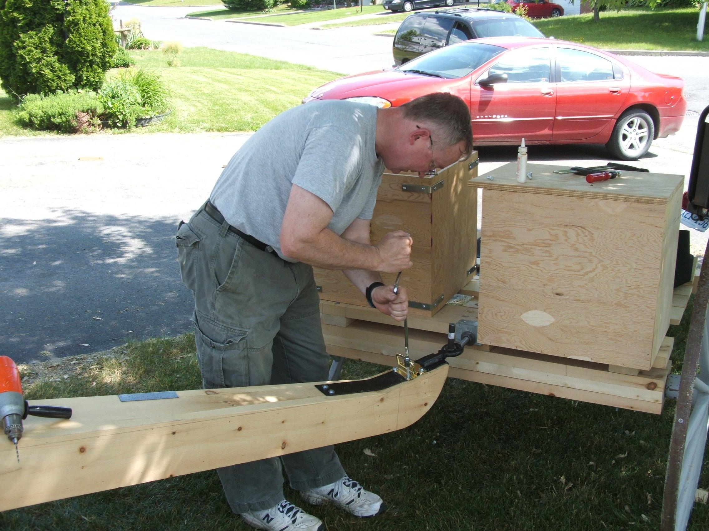
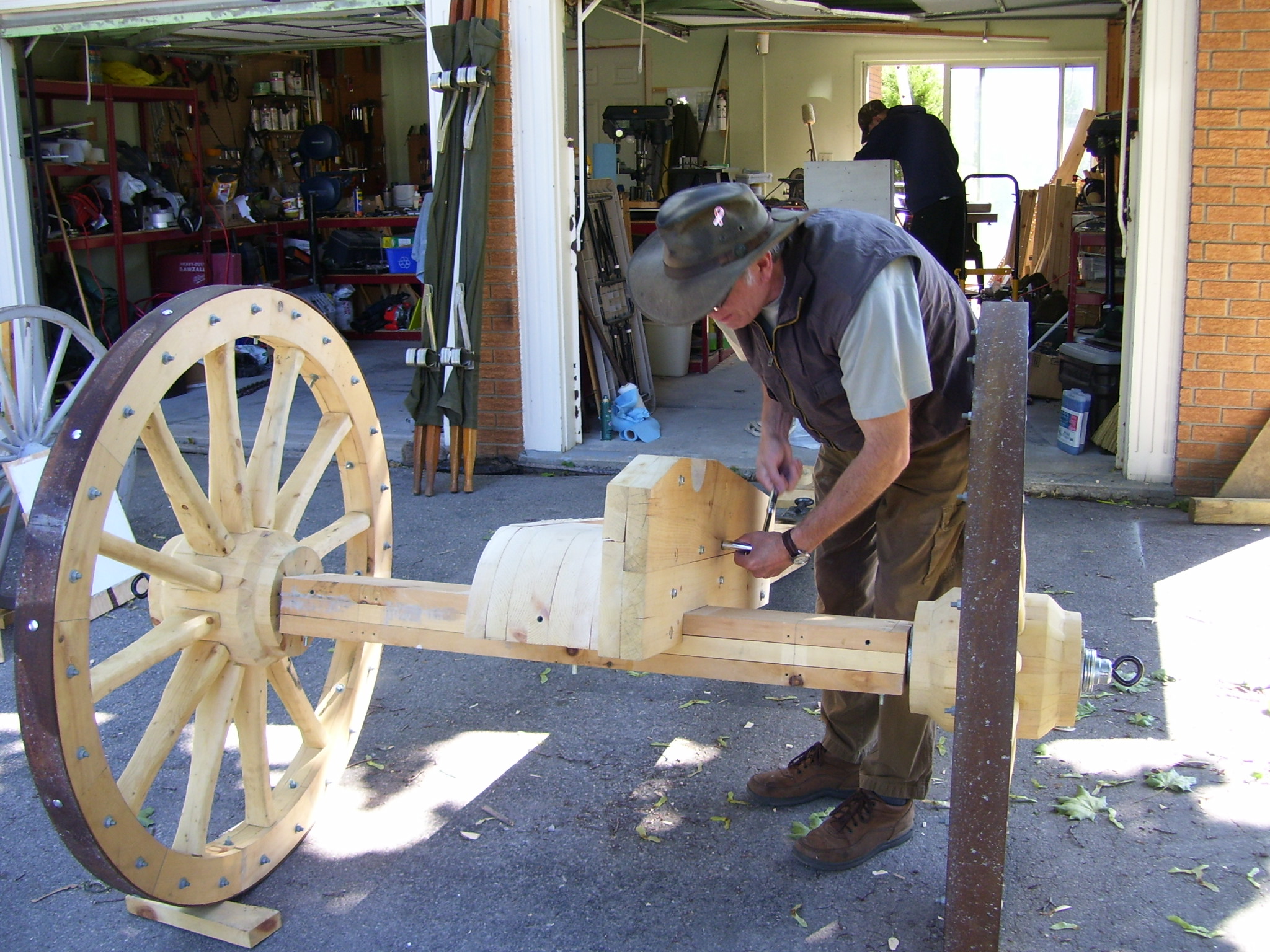
Step 6: Build the gun carriage
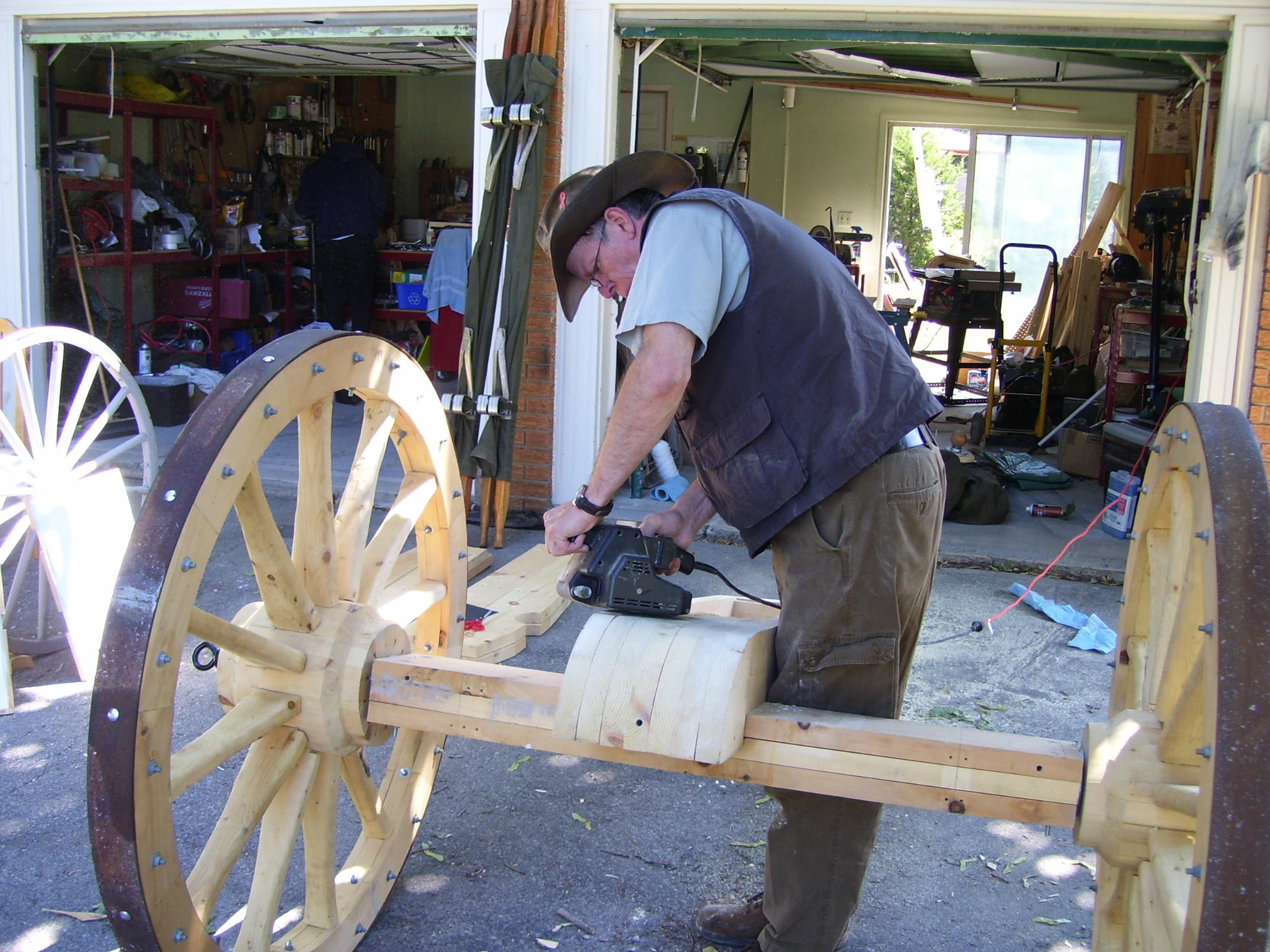
The gun carriage axletree and trail was fabricated out of 2”x6” and 2”x8” select pine to keep the weight down.
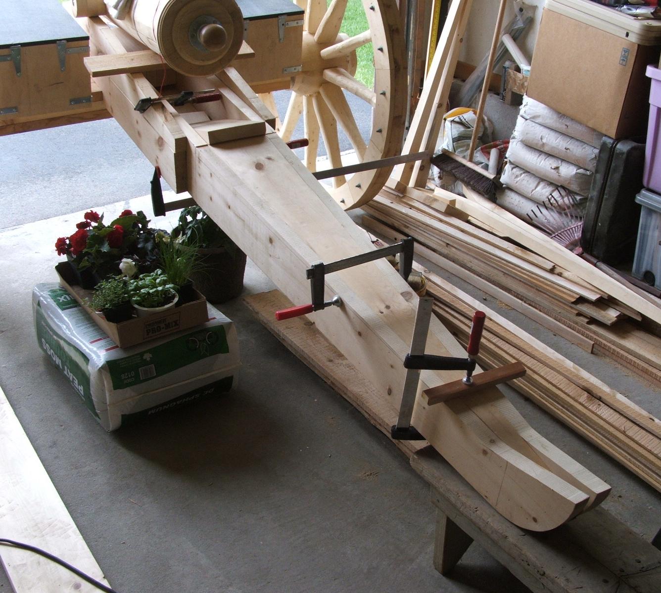
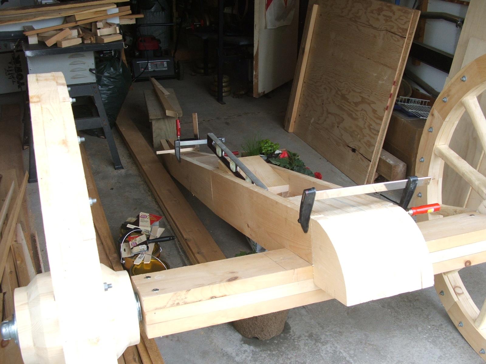
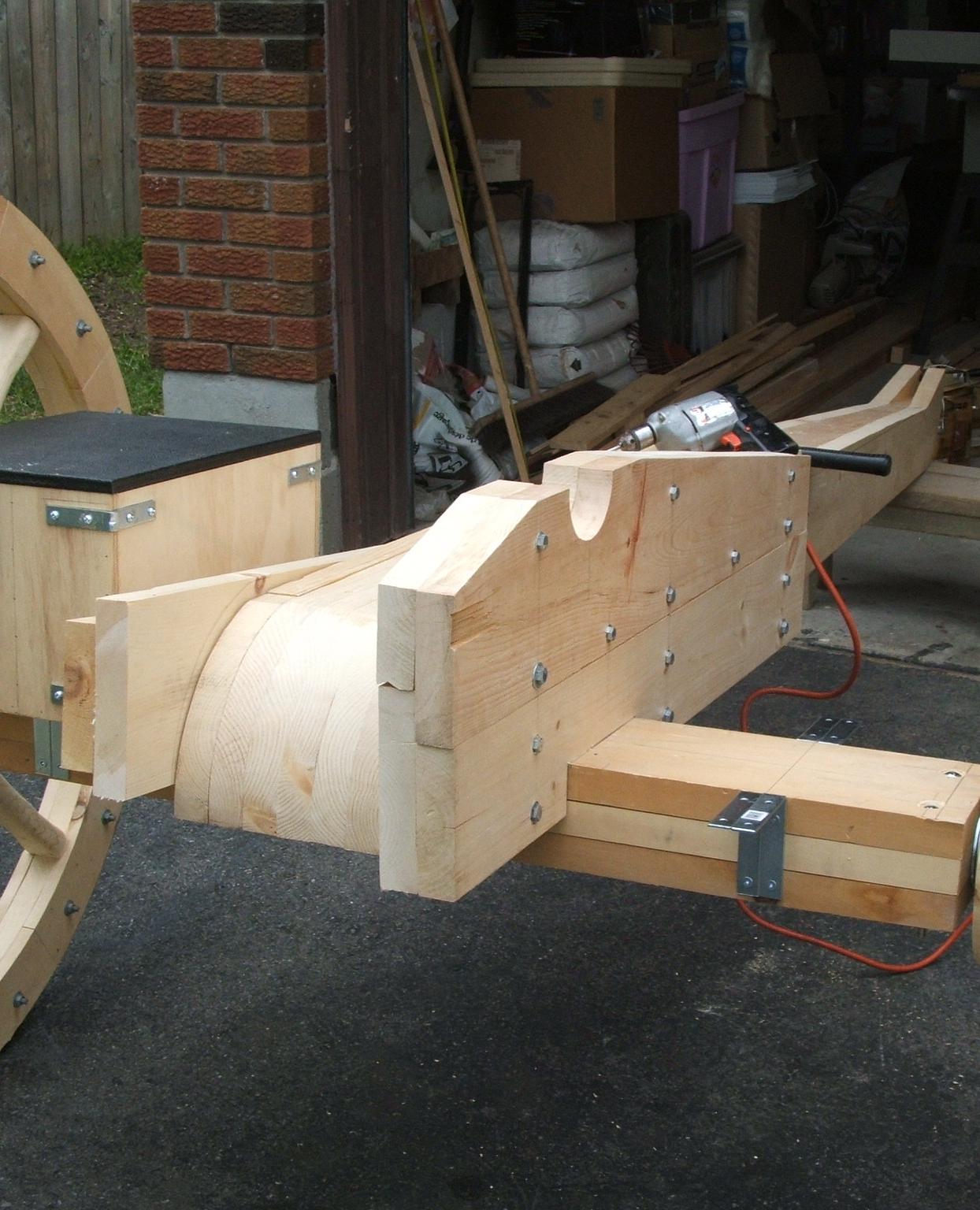

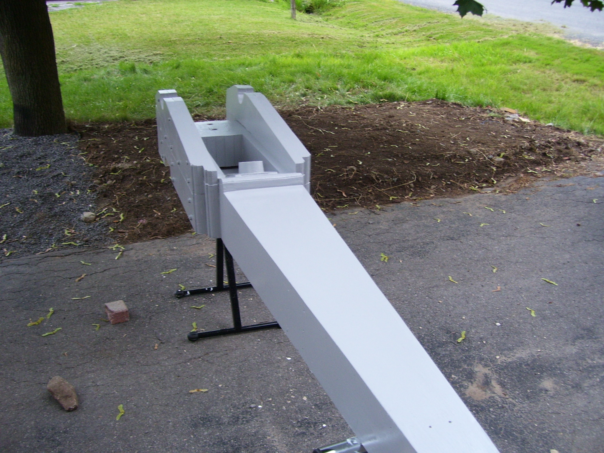
The axletree is composed of 2x6 and 2x4 planks through which a 1” steel pipe axle is run. Each end of the axletree has a 1.25” flange and short-nipple bearing, to secure the axle and to keep it from wearing away the wood.
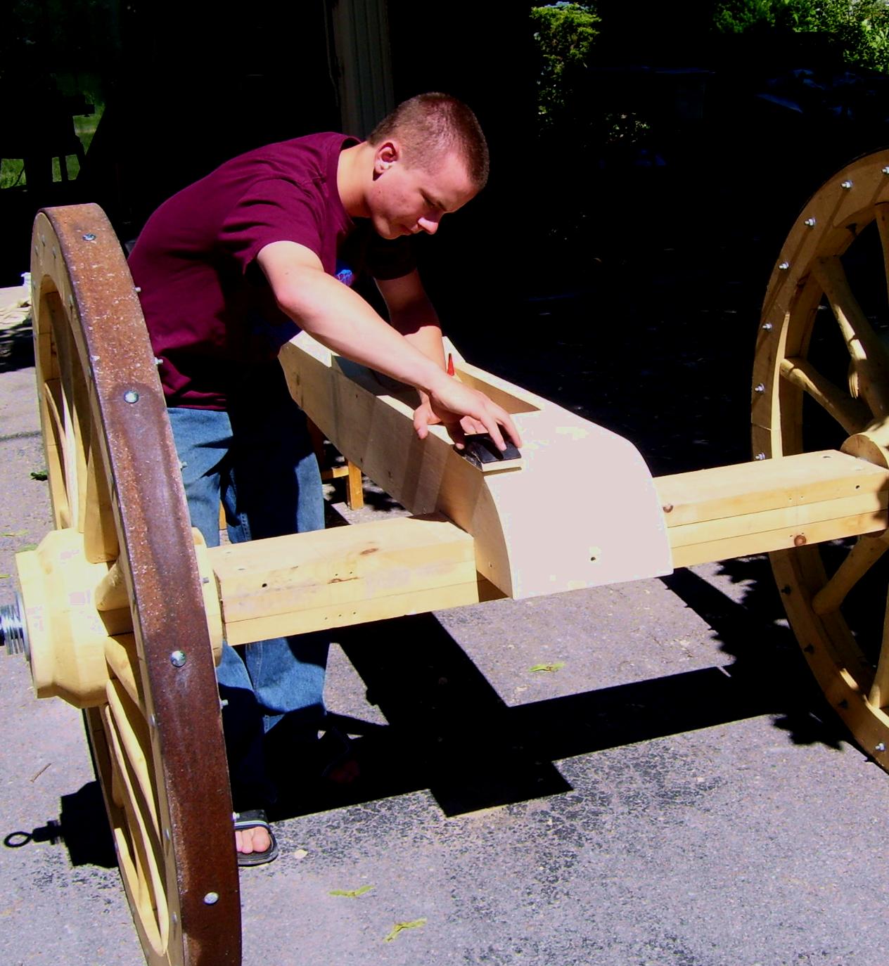
The gun trunnion mounts, the cheeks, were fabricated from 2x6” and 2x8” planks shaped, laminated together and fitted to the trail. Initially these were clamped in place so measurements for the position of the trunnion supports, the elevation mechanism and the ammunition boxes could be verified.
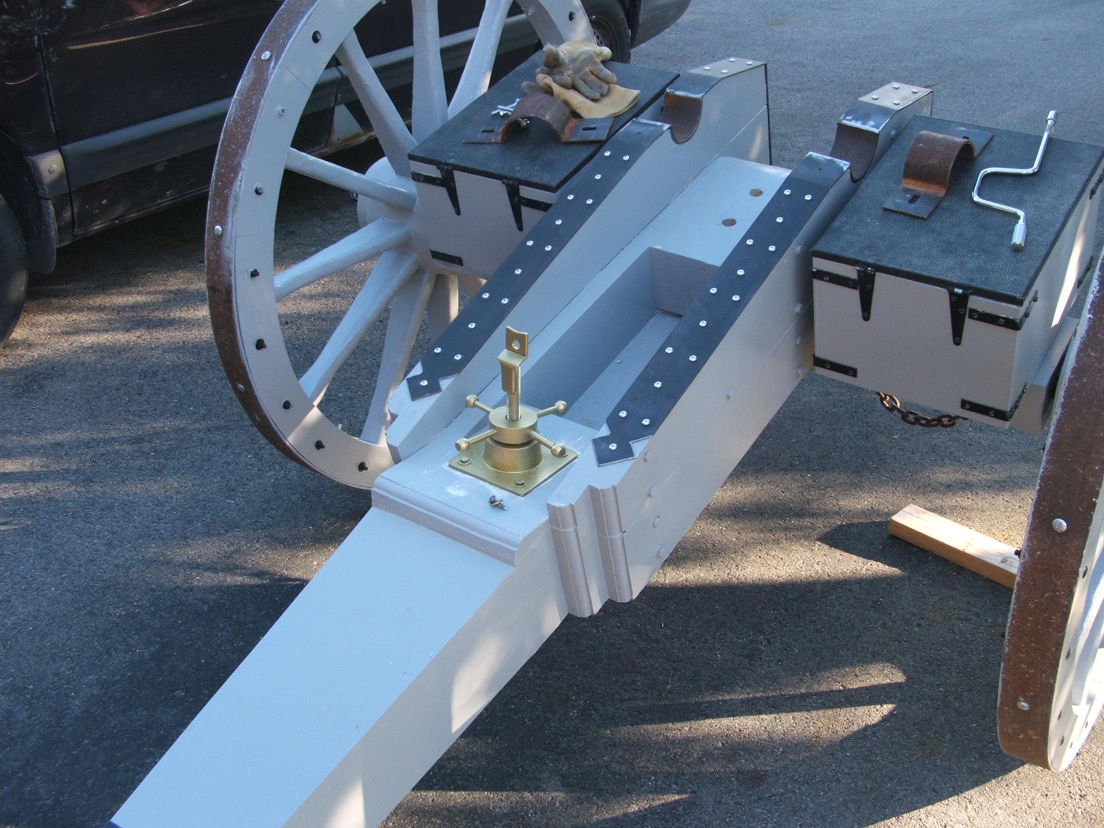
Step 7: Adding the Elevation Jackscrew
The elevation jackscrew was fabricated from a ¾” bolt attached to the breach of the gun in a way that permitted access to the gun chamber. The nut was encased in a wood ring, with handles for ease of raising and lowering. The nut assembly rests on a platen affixed to the trail.
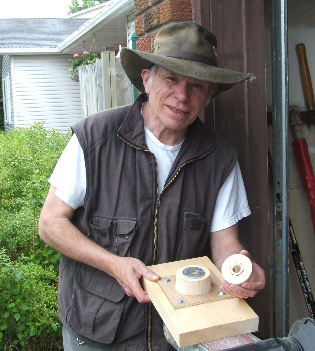
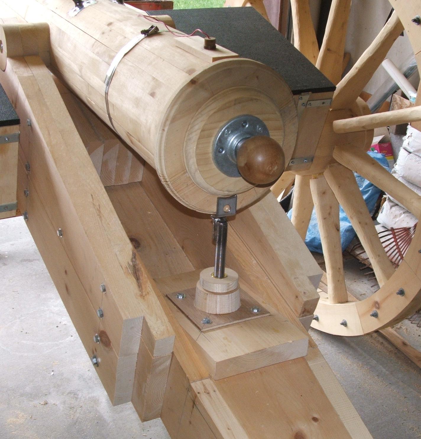
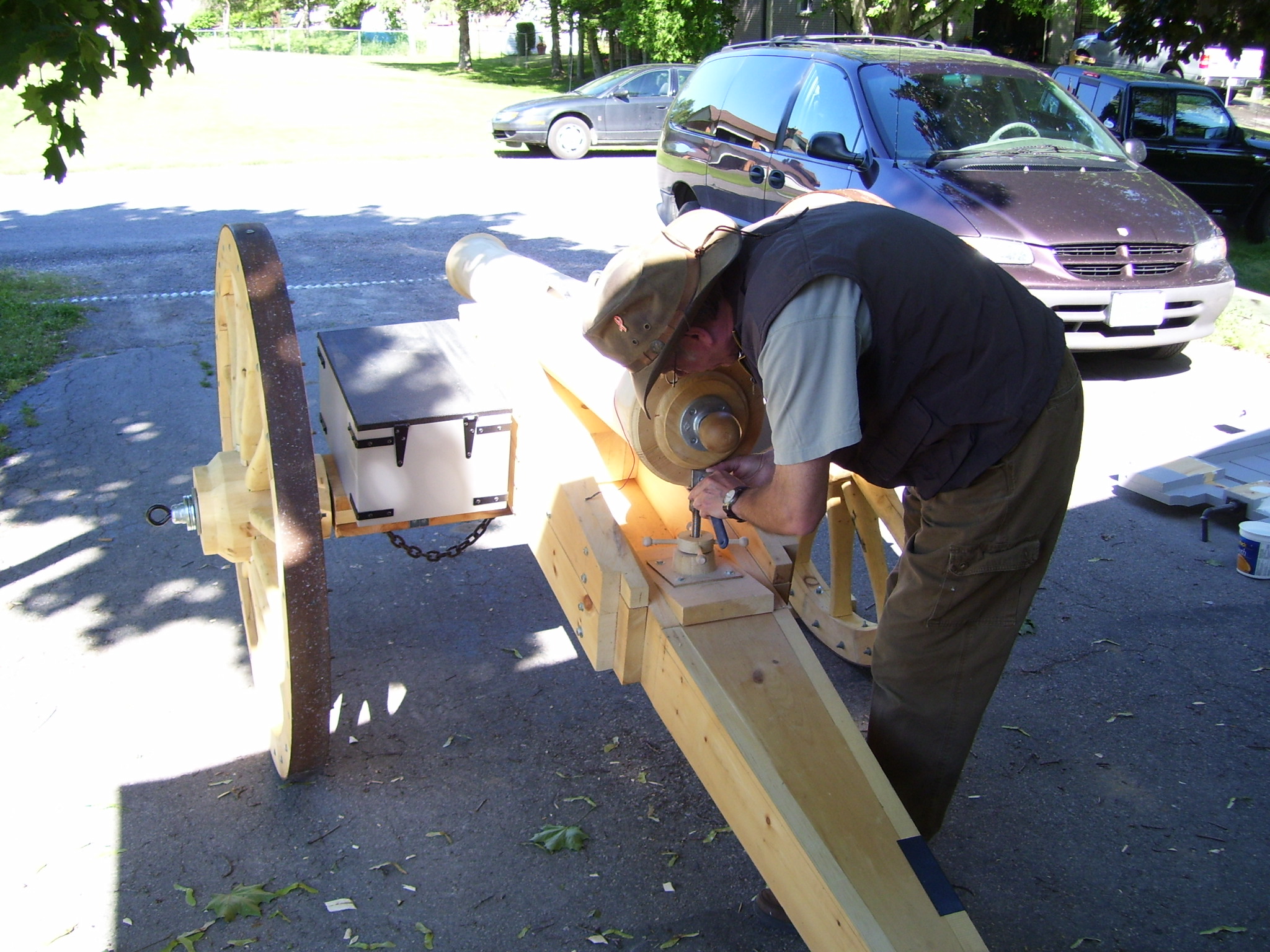
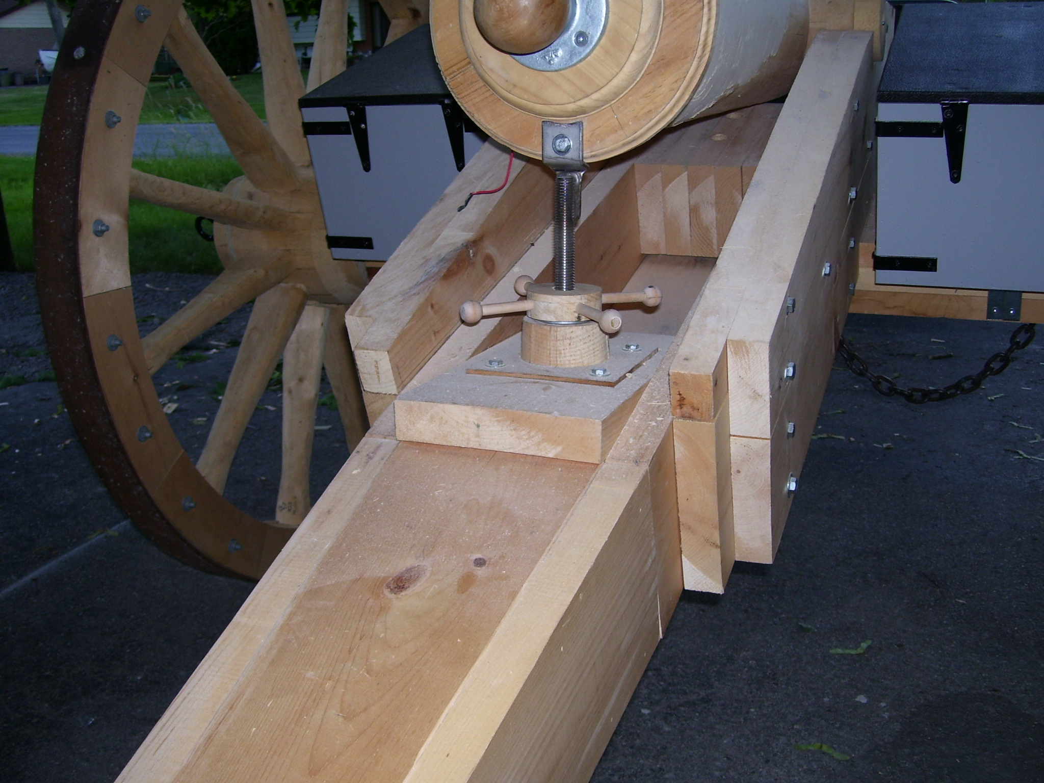

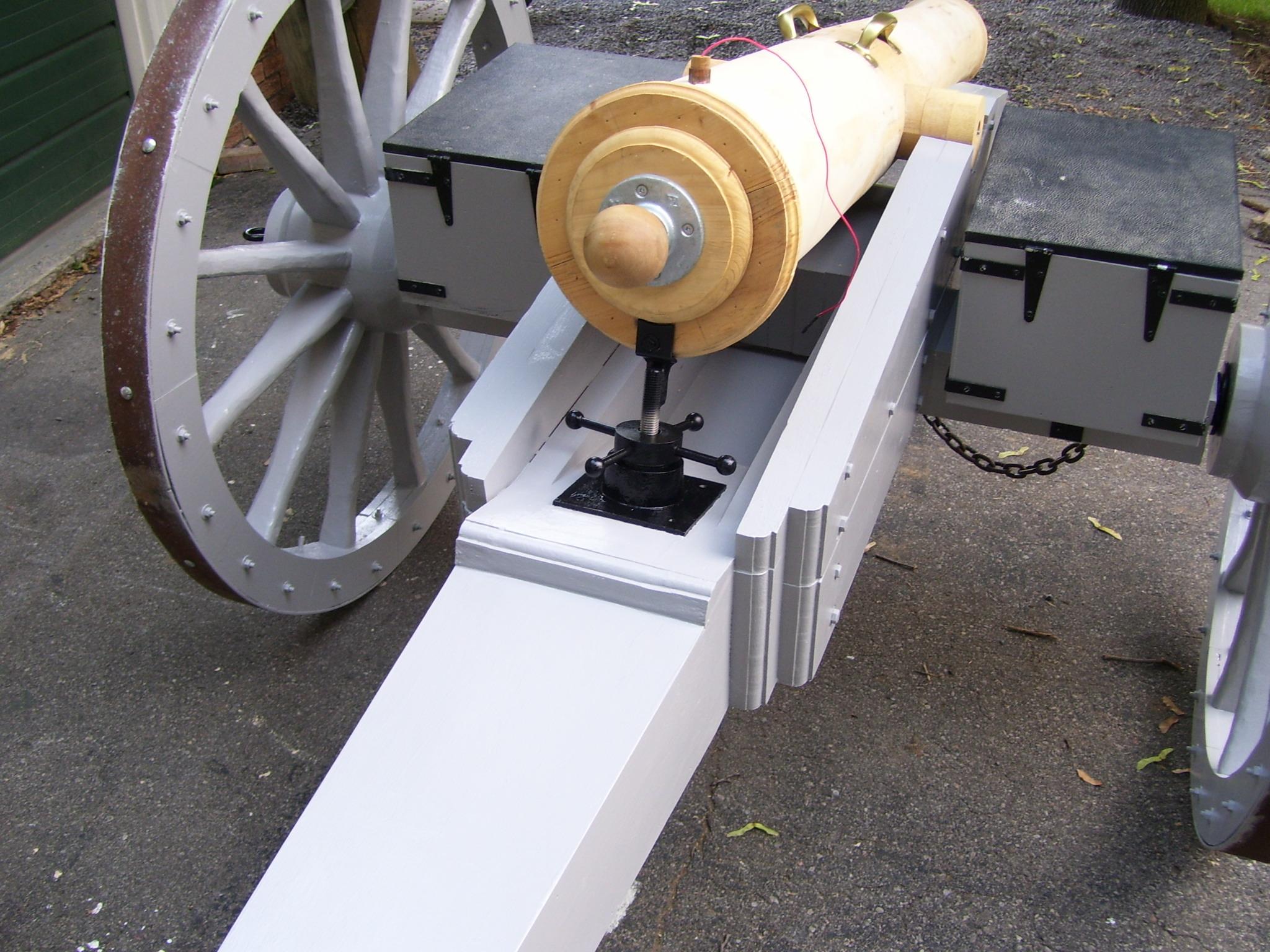
The jackscrew is painted a bright brass.
The gun is raised or lowered by turning the handles forcing the nut to rise or descend against the platen, lowering or raising the breech accordingly.
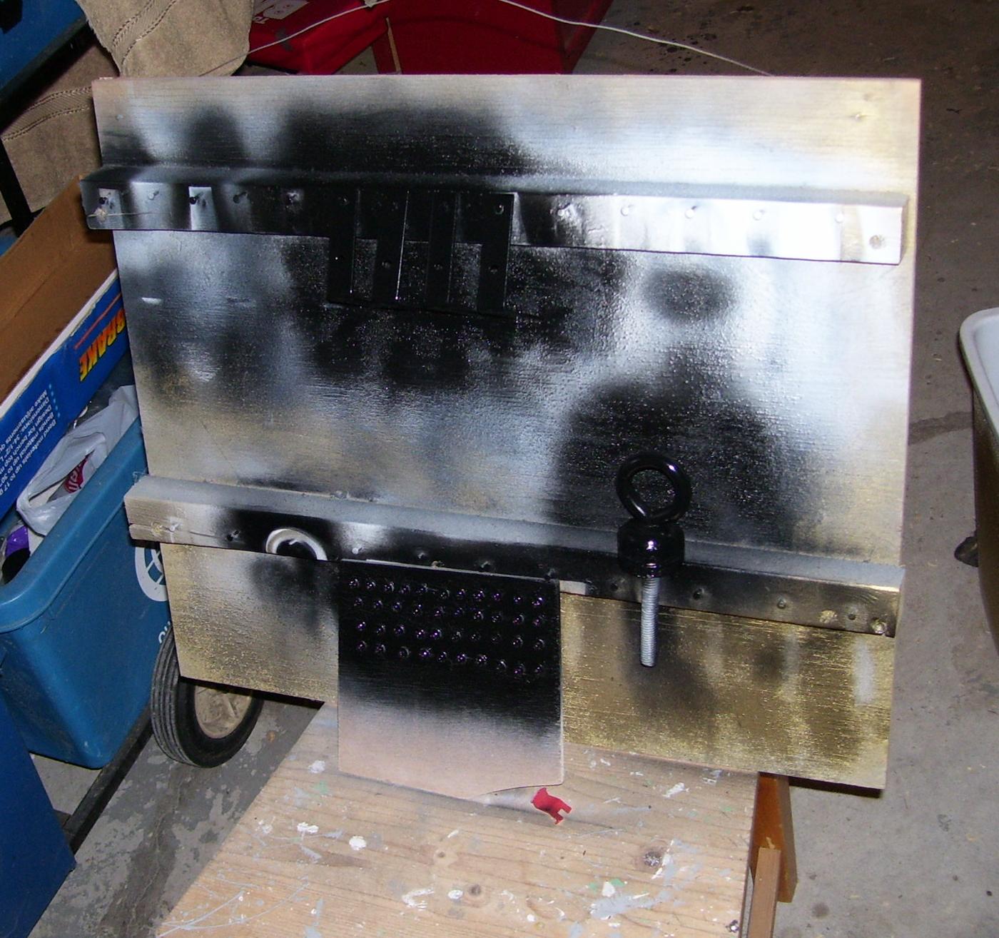
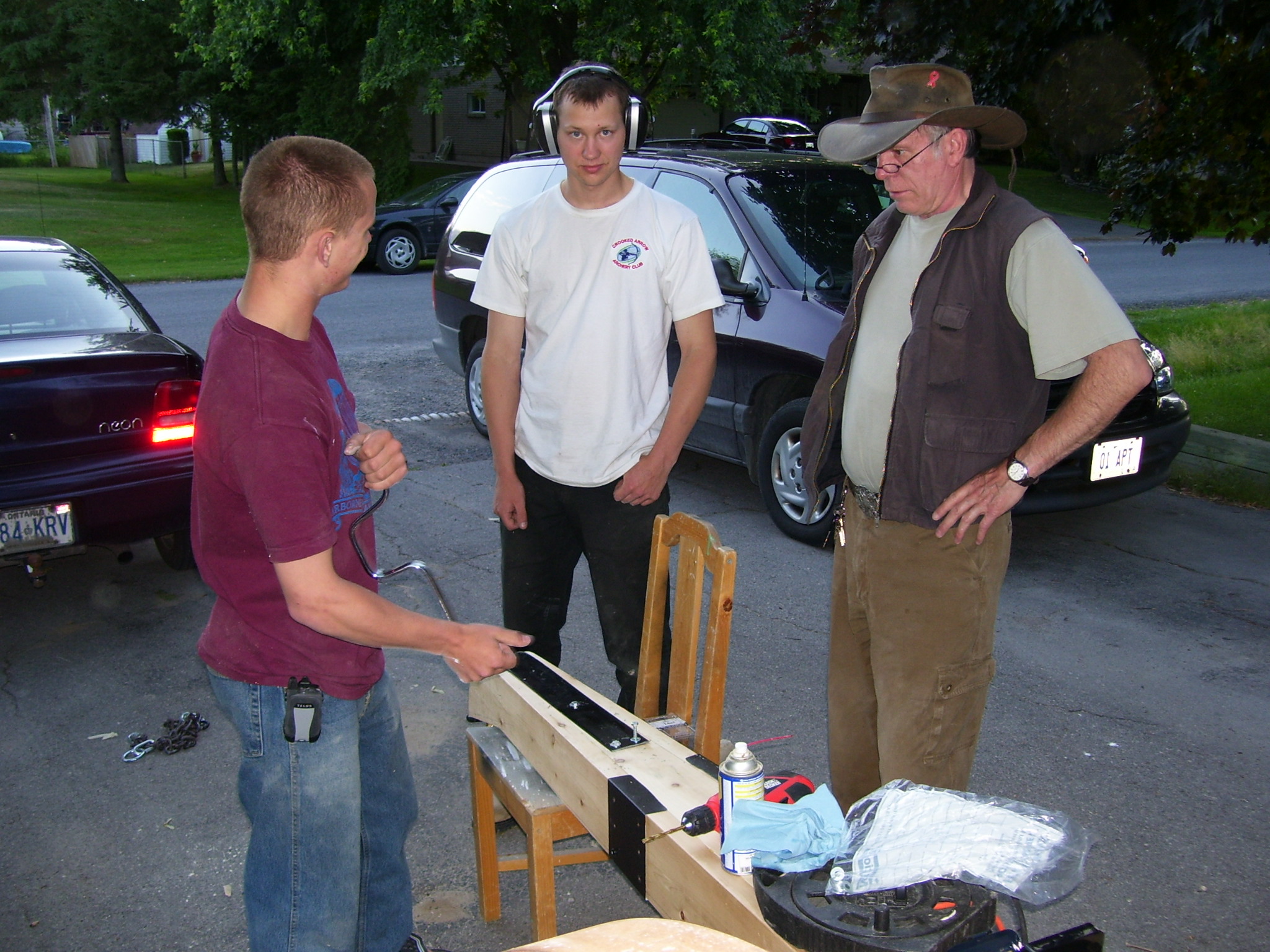
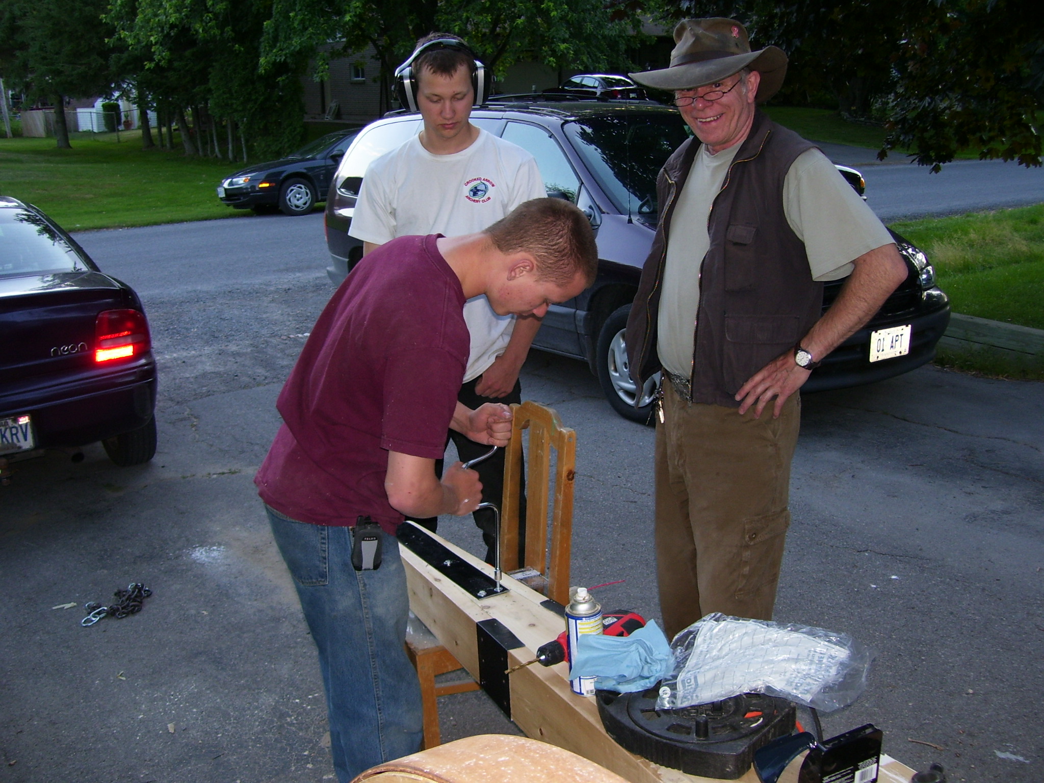
Step 8: Adding the Trunnion support Hardware
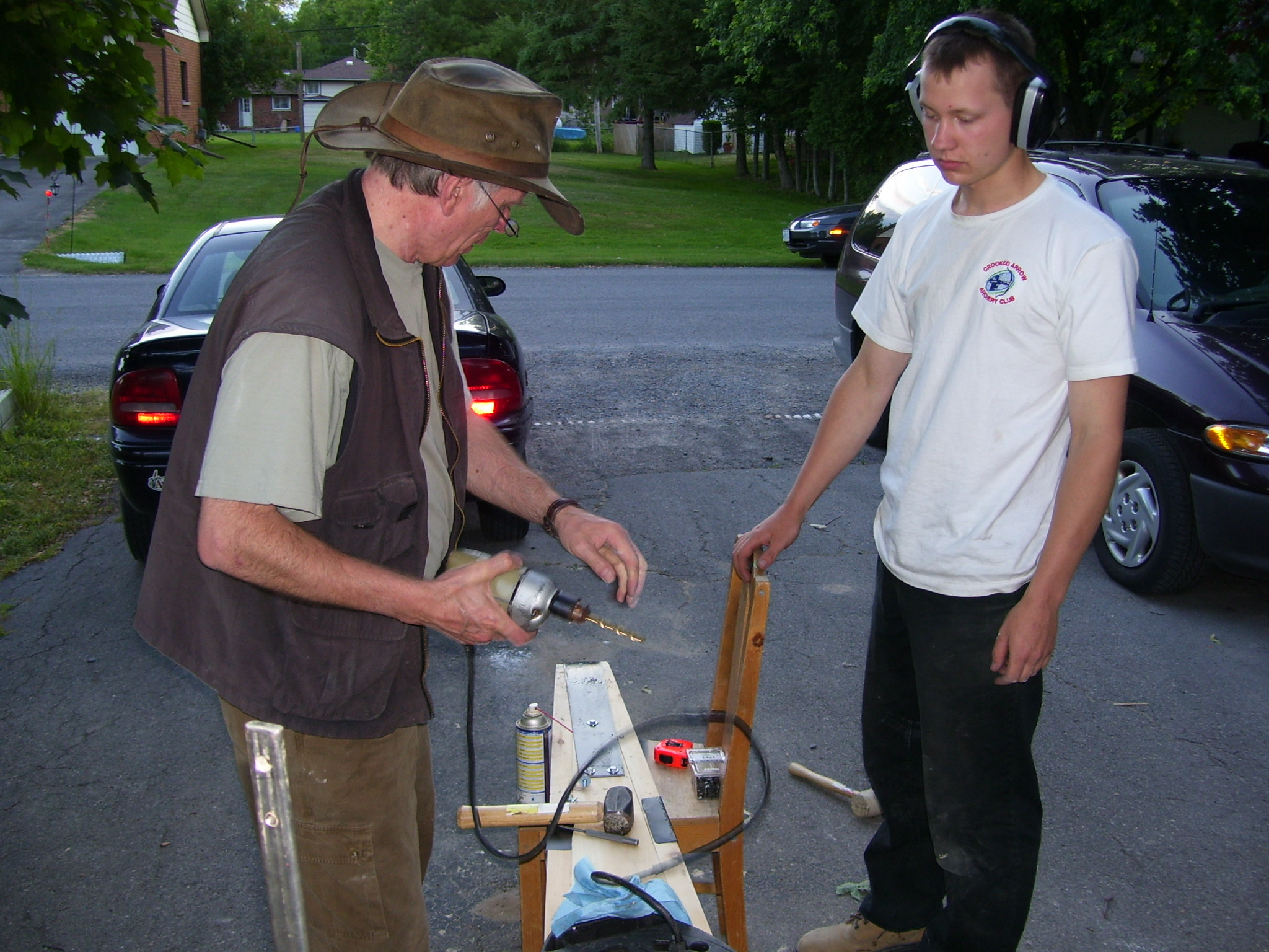
The trunnion supports, and capture flange were fabricated from 3”x1/8” flat steel welded to ½ of a 3” piece of 4” pipe.
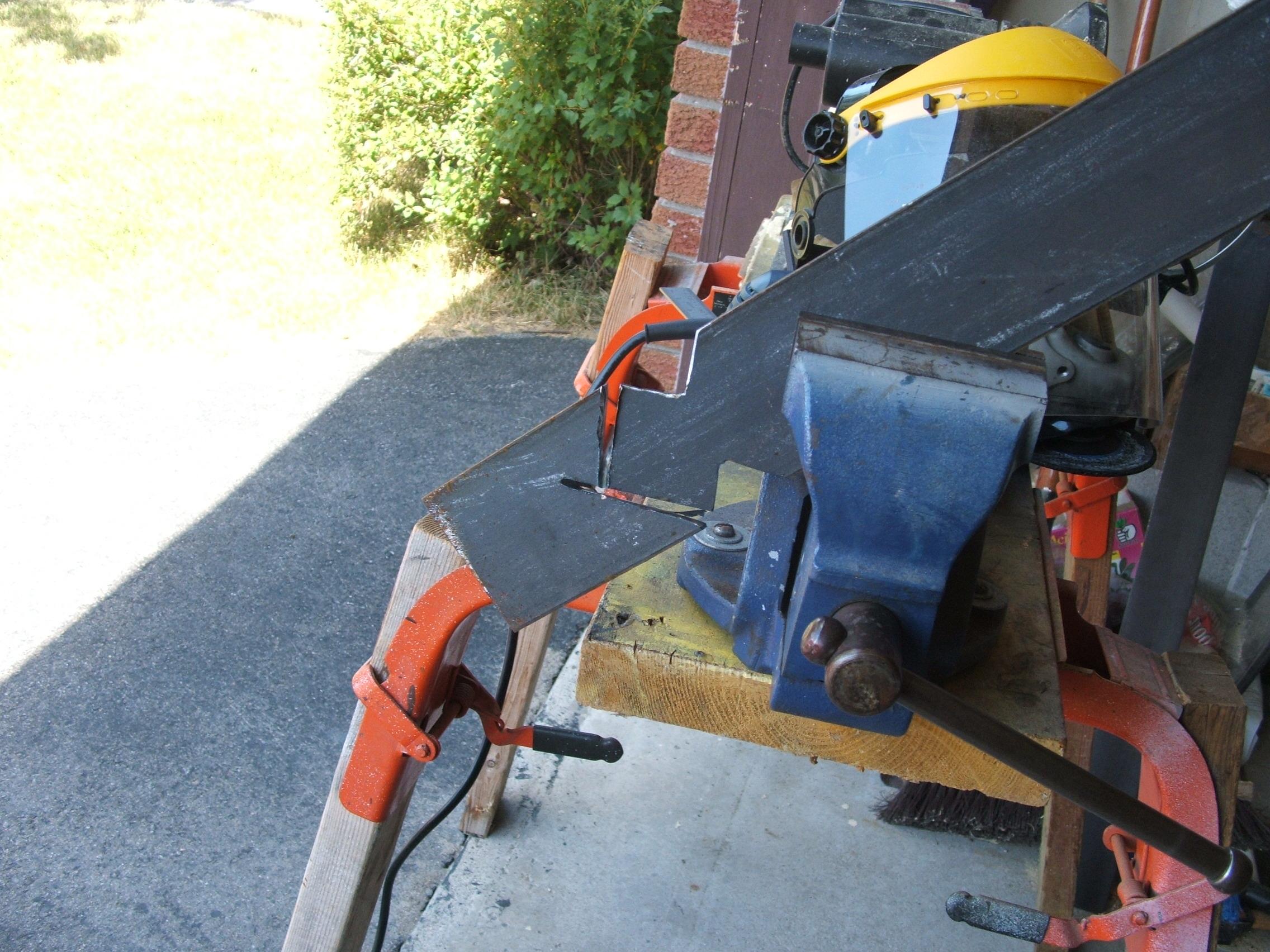
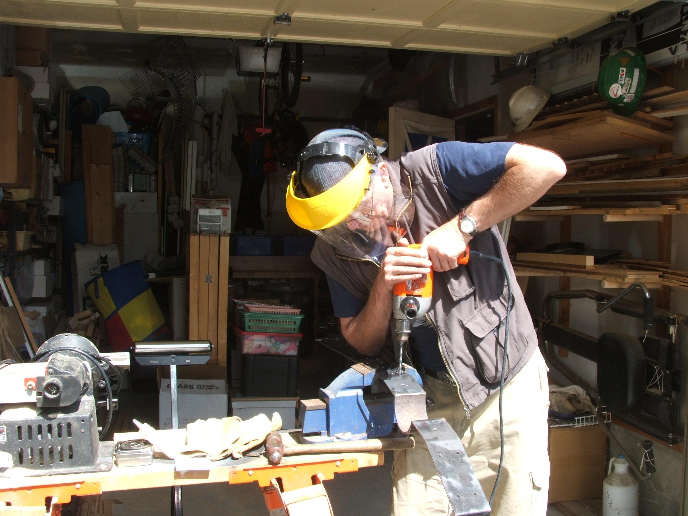
Cutting and welding needs to be carefully done so the brackets form a 4” circle to accurately fit the trunnions and are perfectly square.
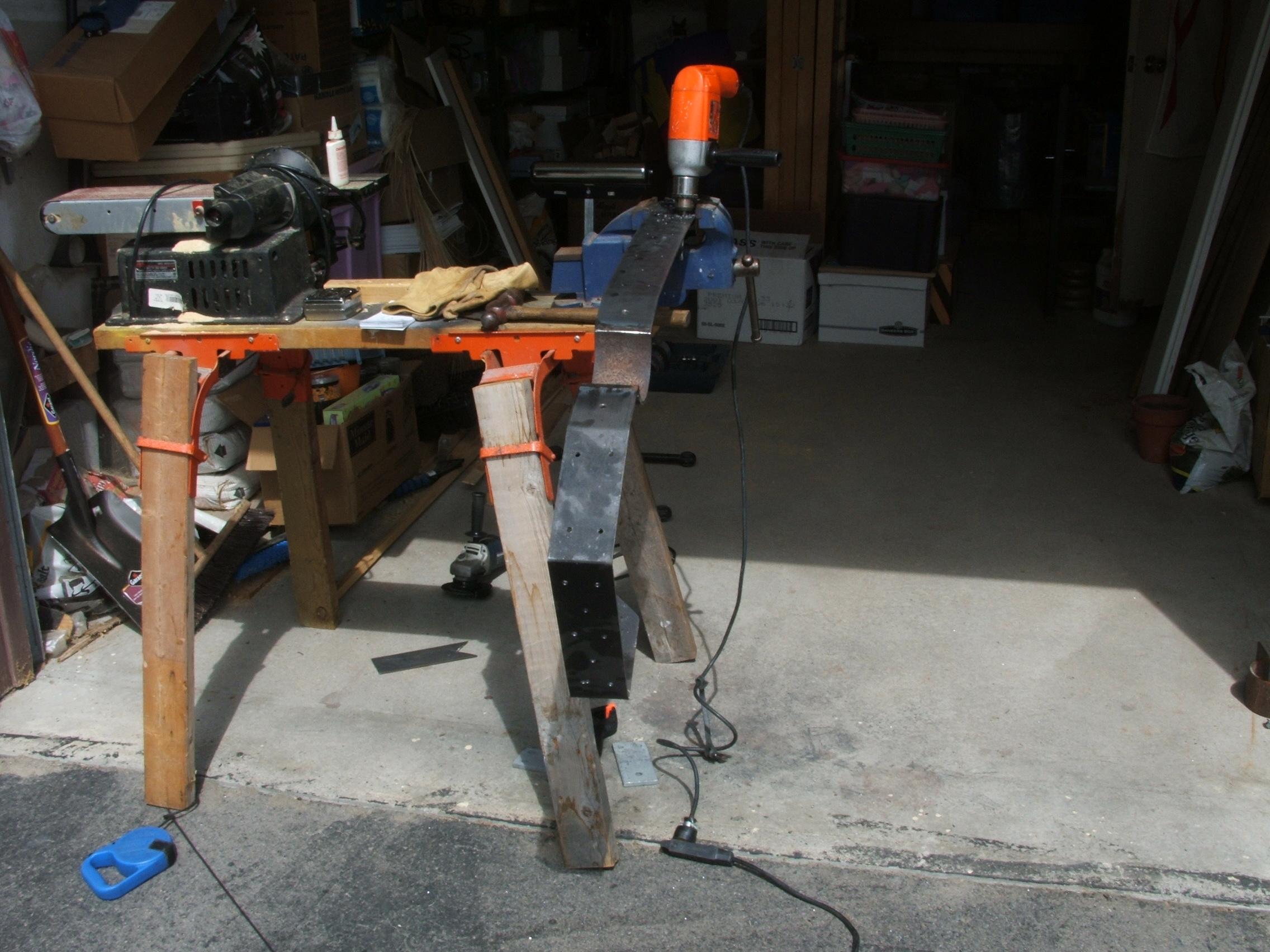
The support iron is bent to fit the shape of the trail cheeks, and drilled for installation. Care must be taken to insure the bends account for the metal thickness, and that the bends are perfectly square.
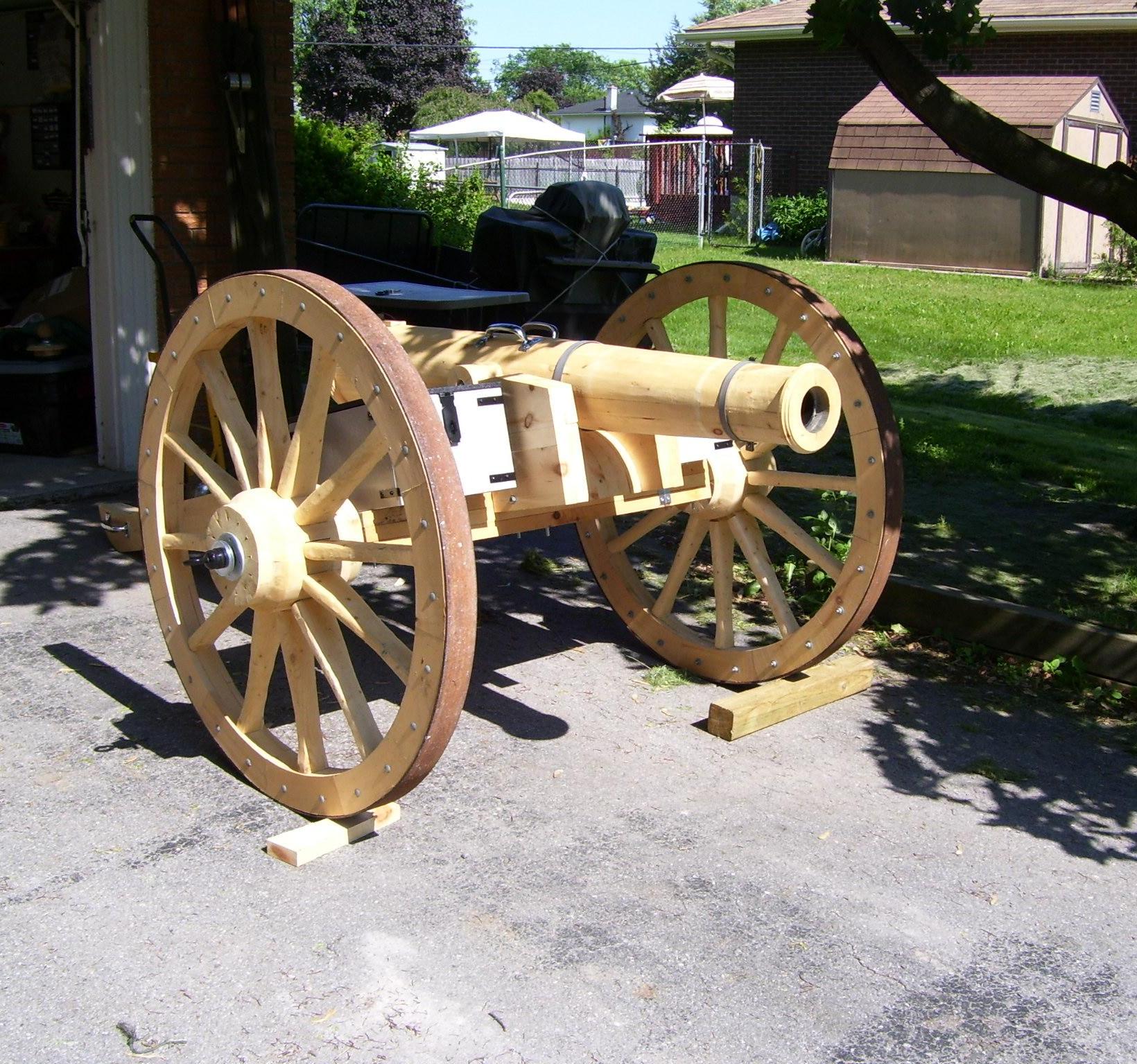
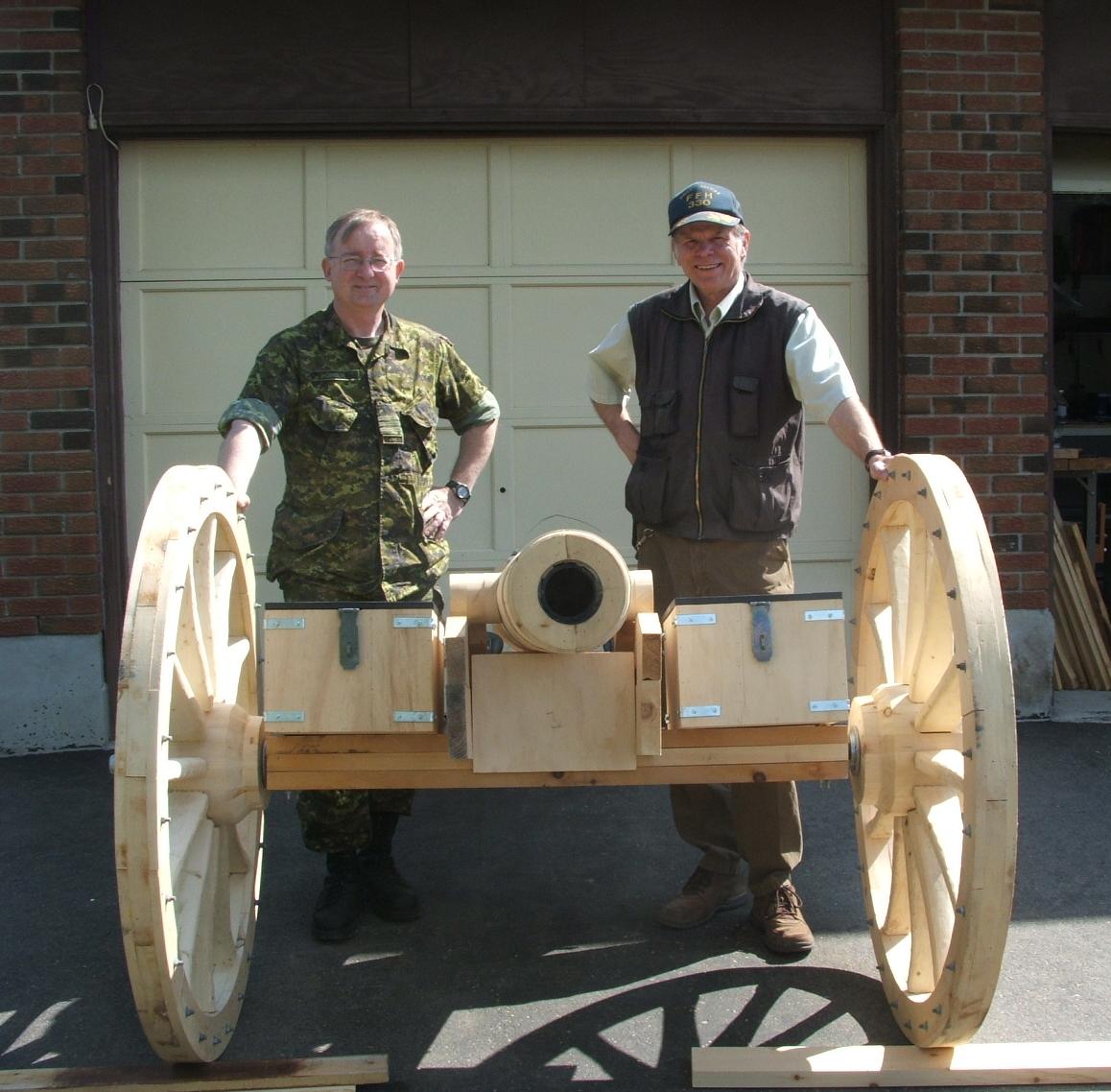
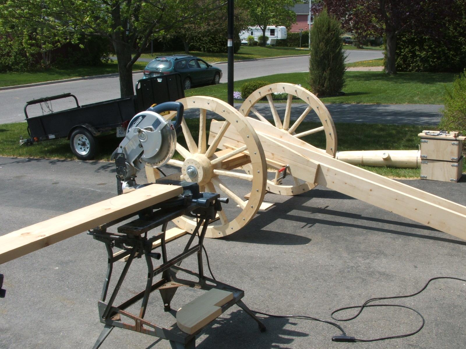
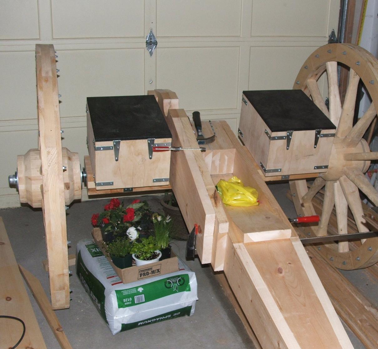
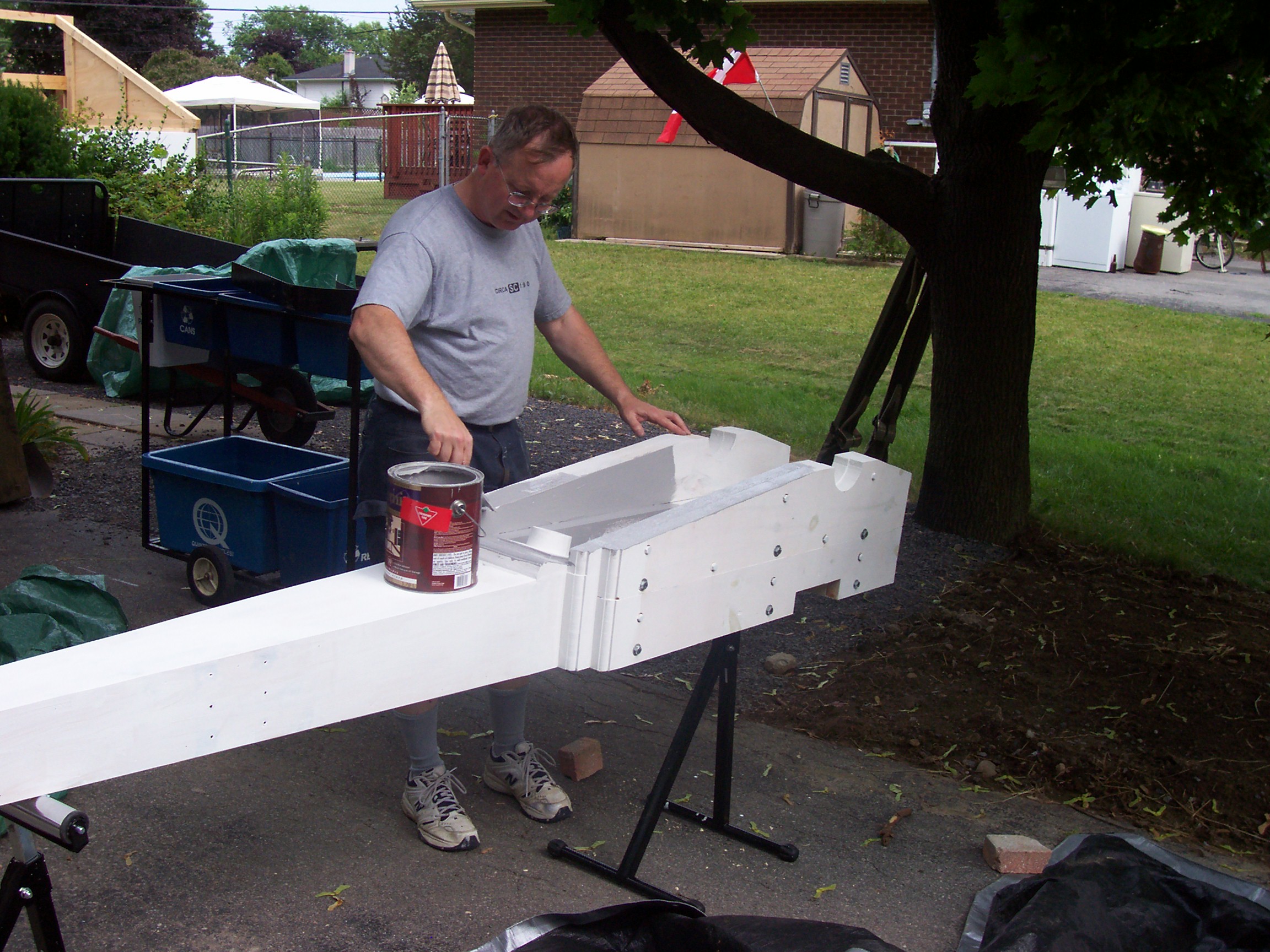
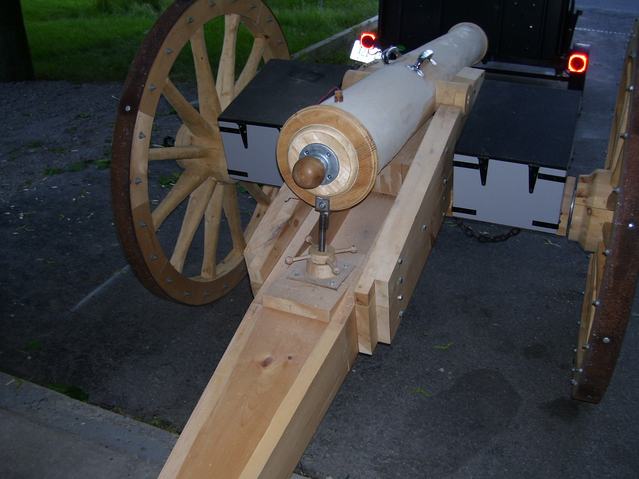
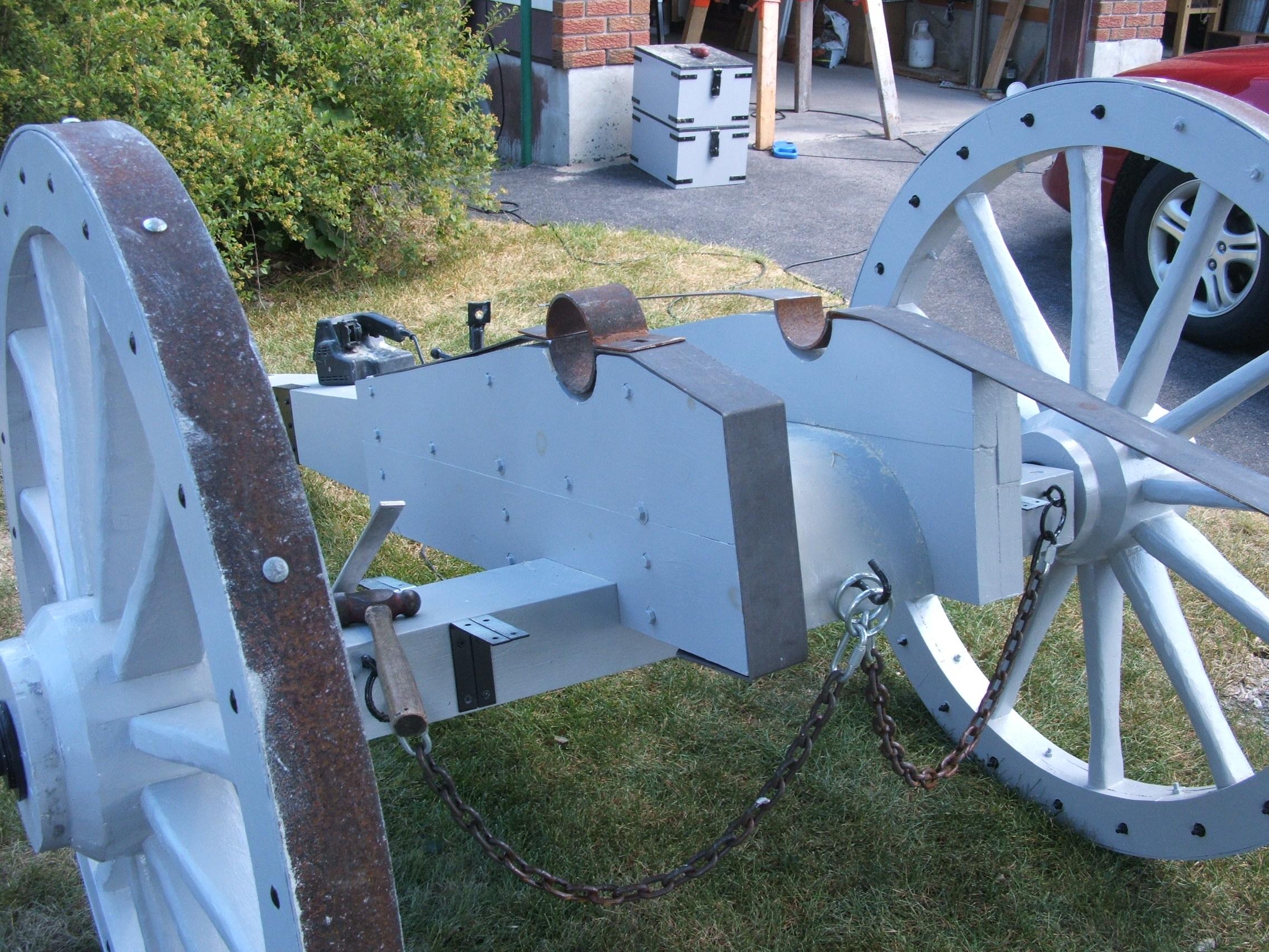
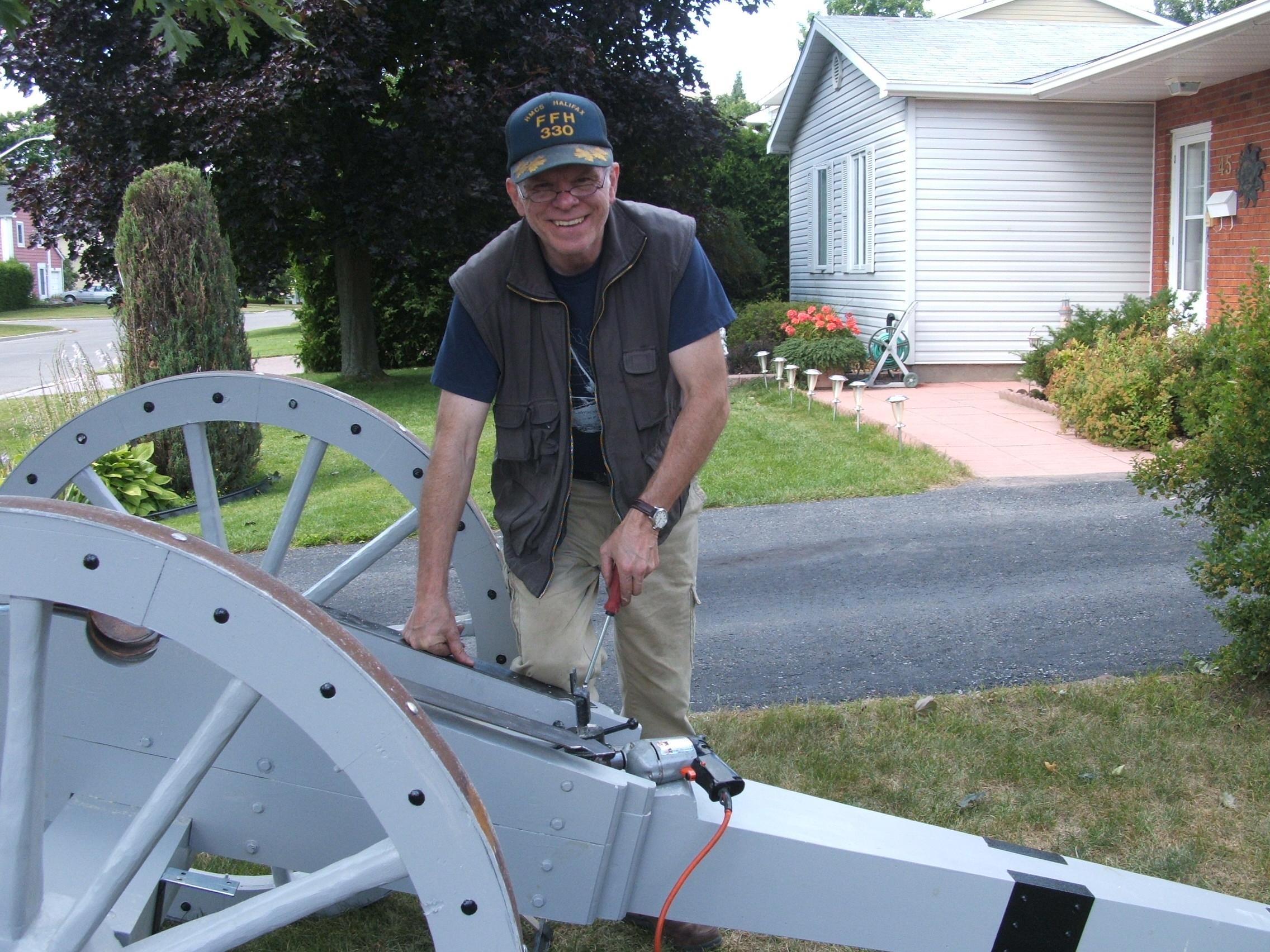
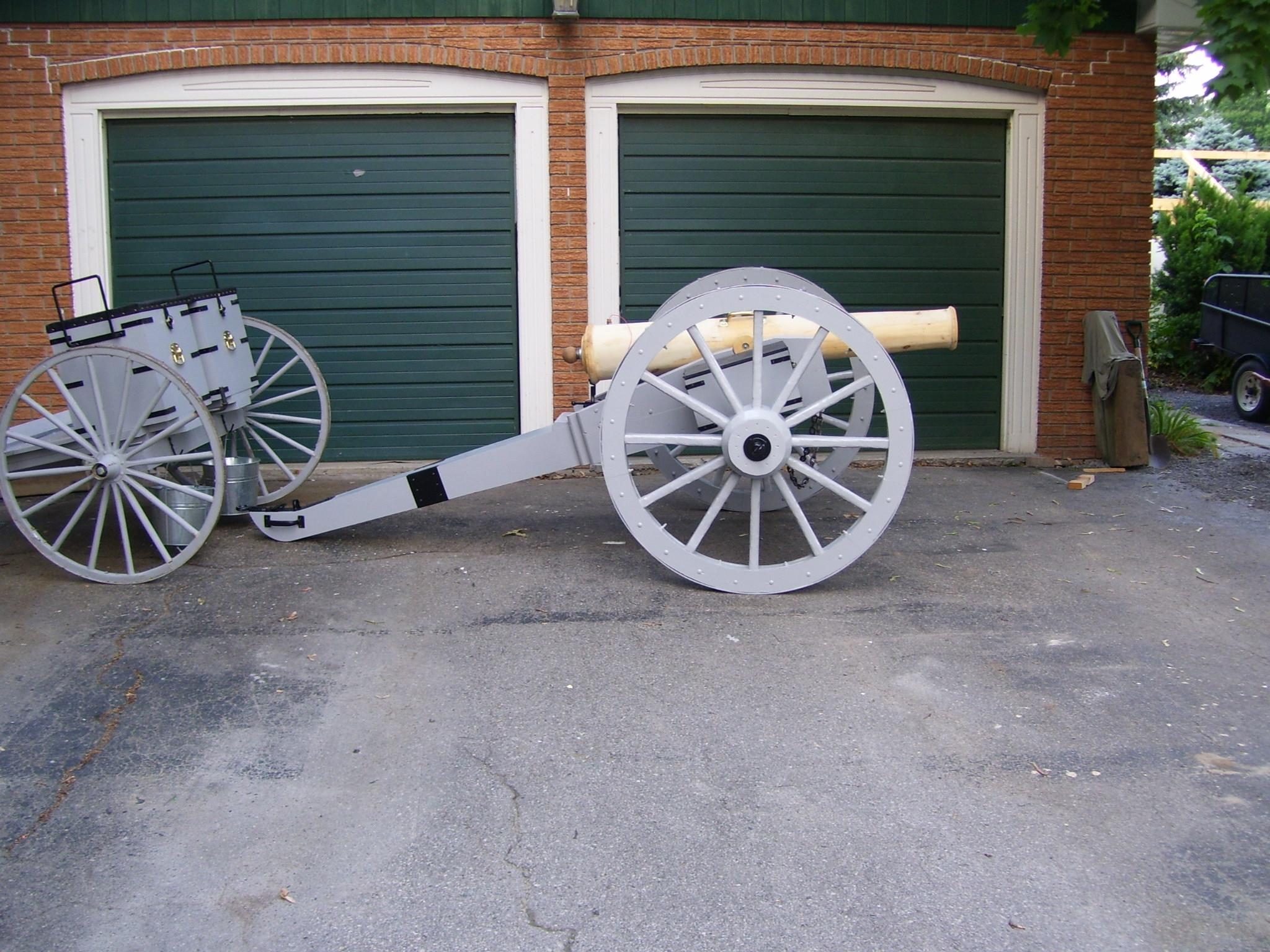
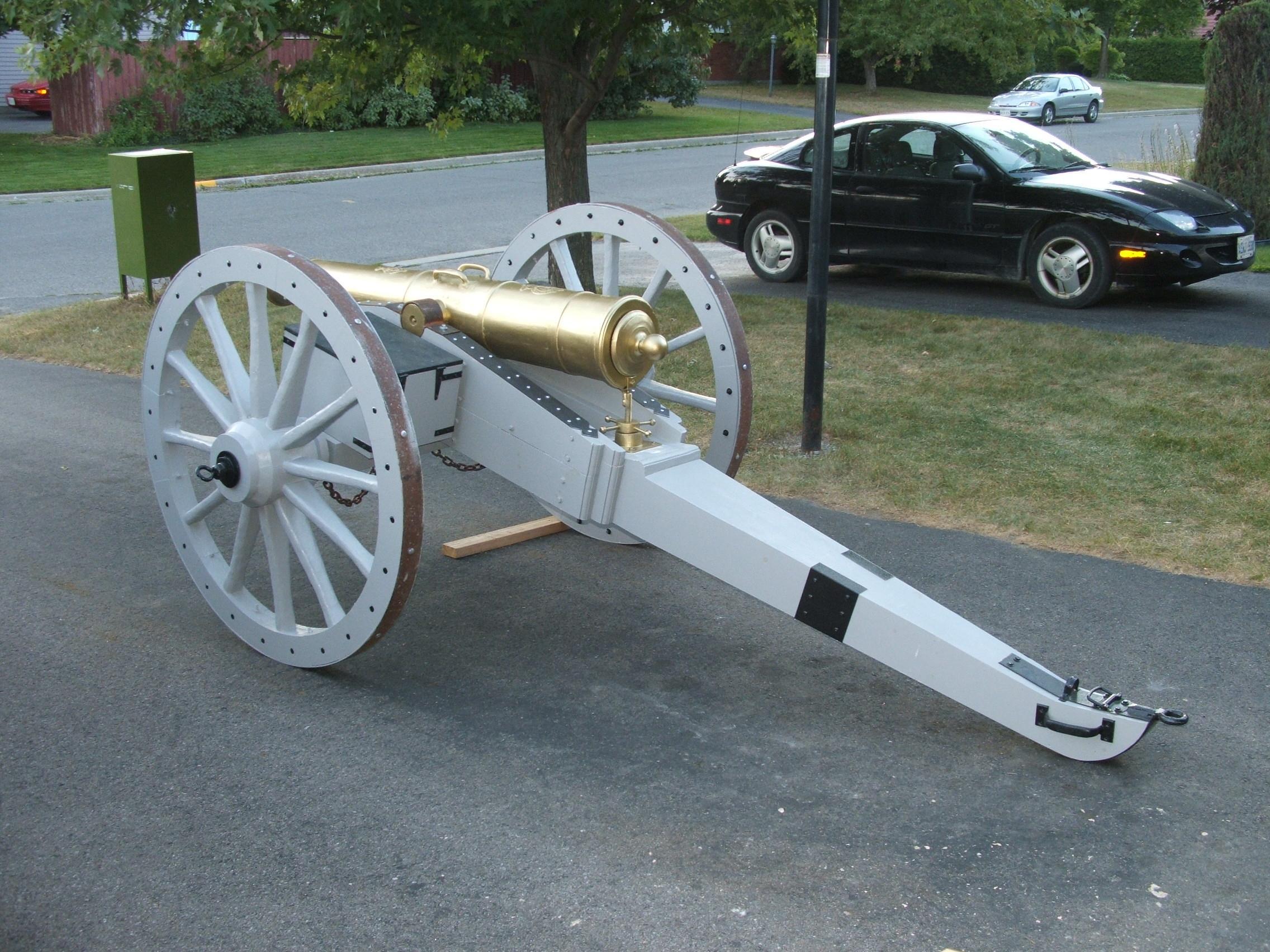
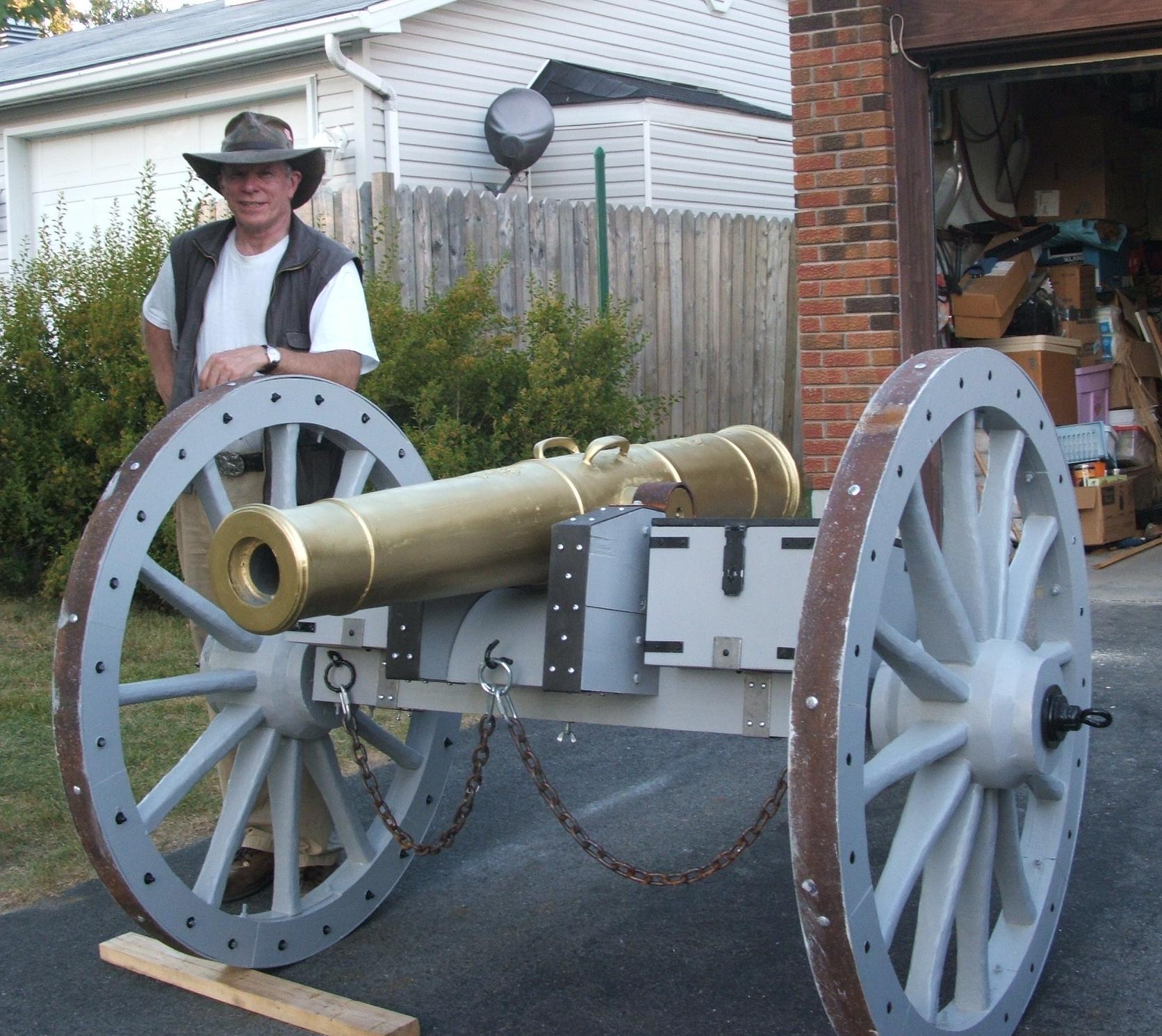
Step 9: Fitting out & Completion
. The trail is complete with the trail skid and towing eye, as well as the steel side panels and fittings.
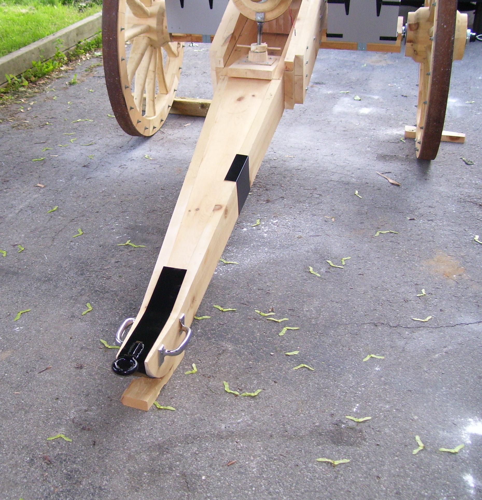
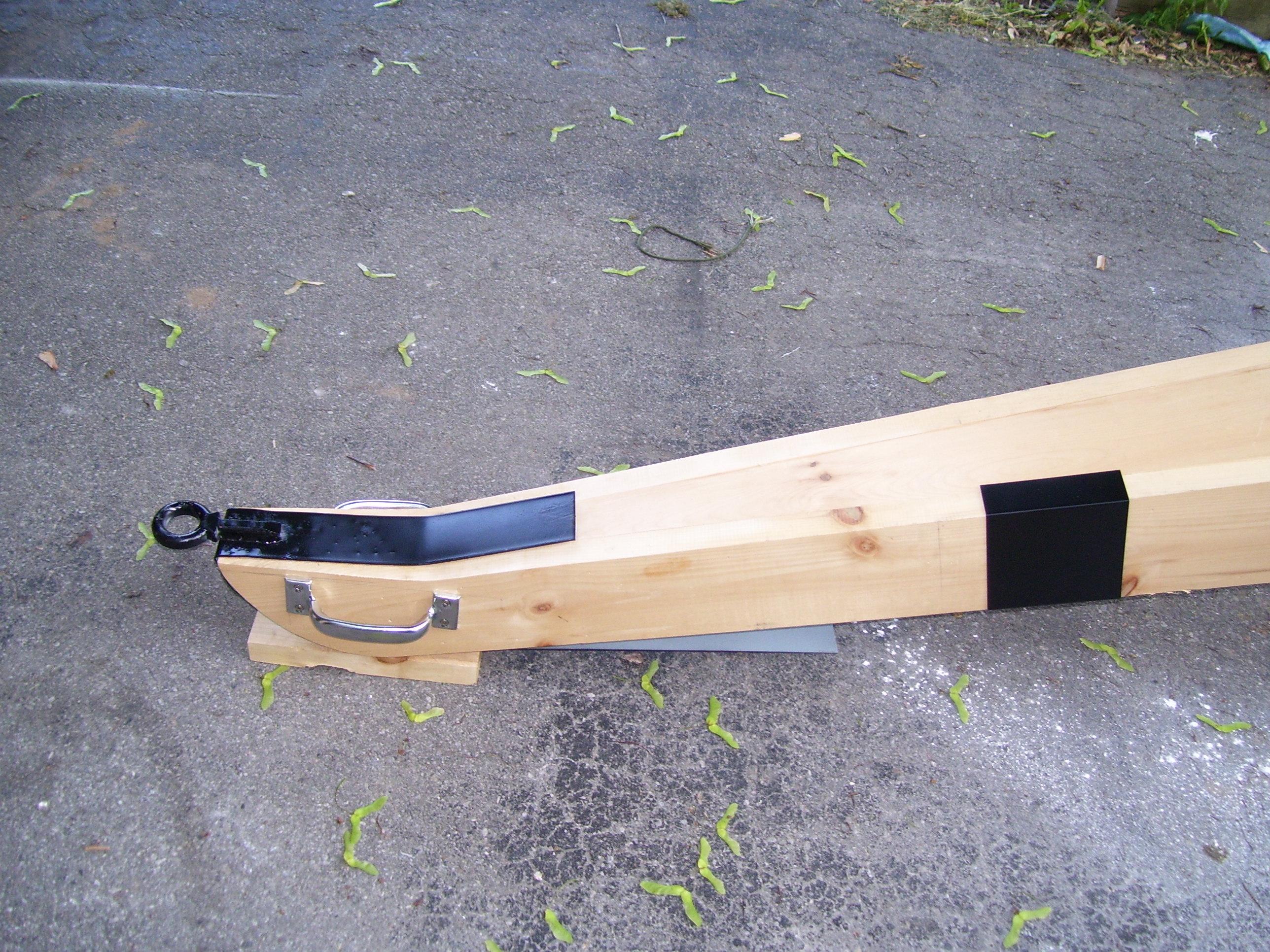

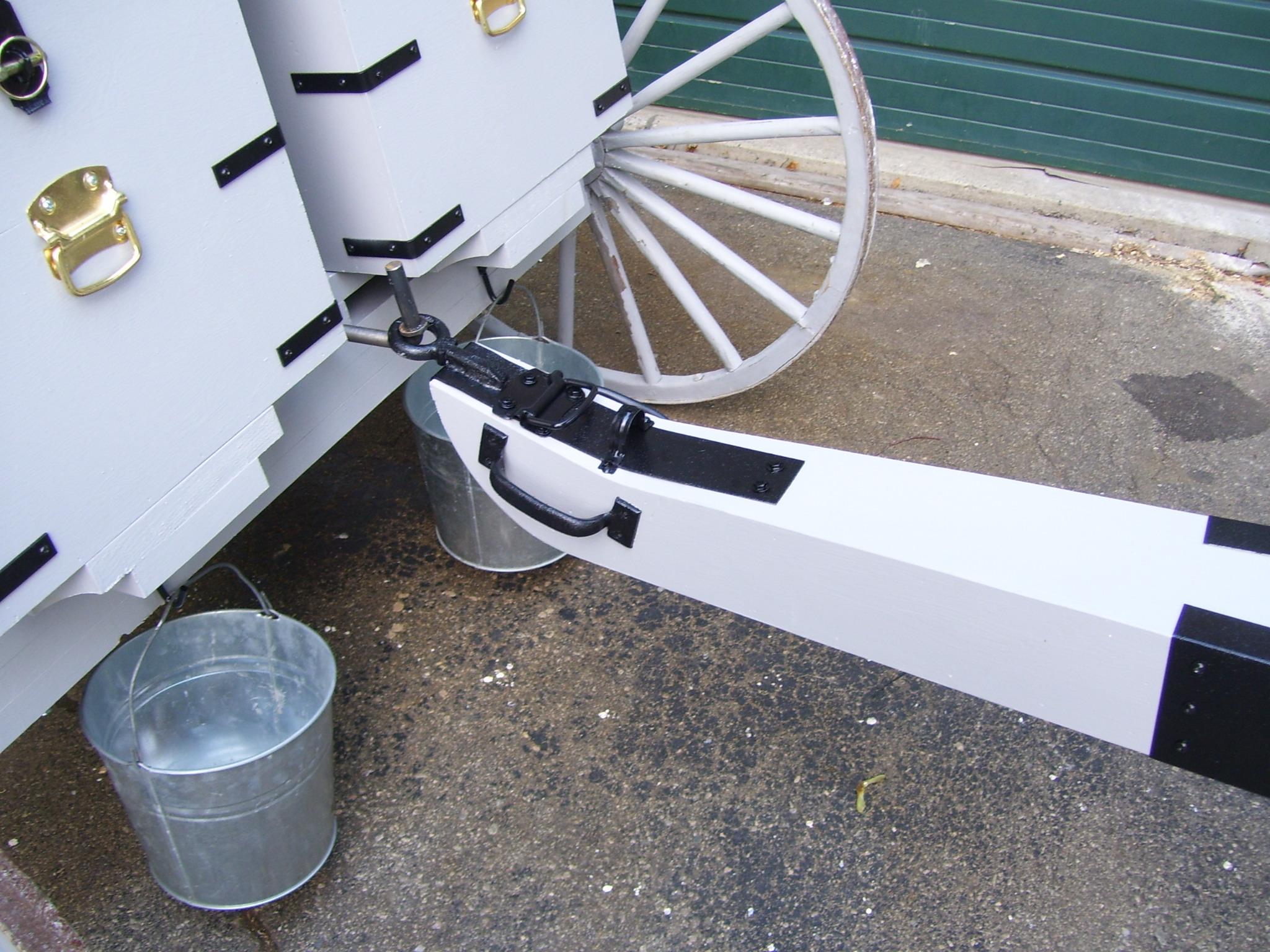
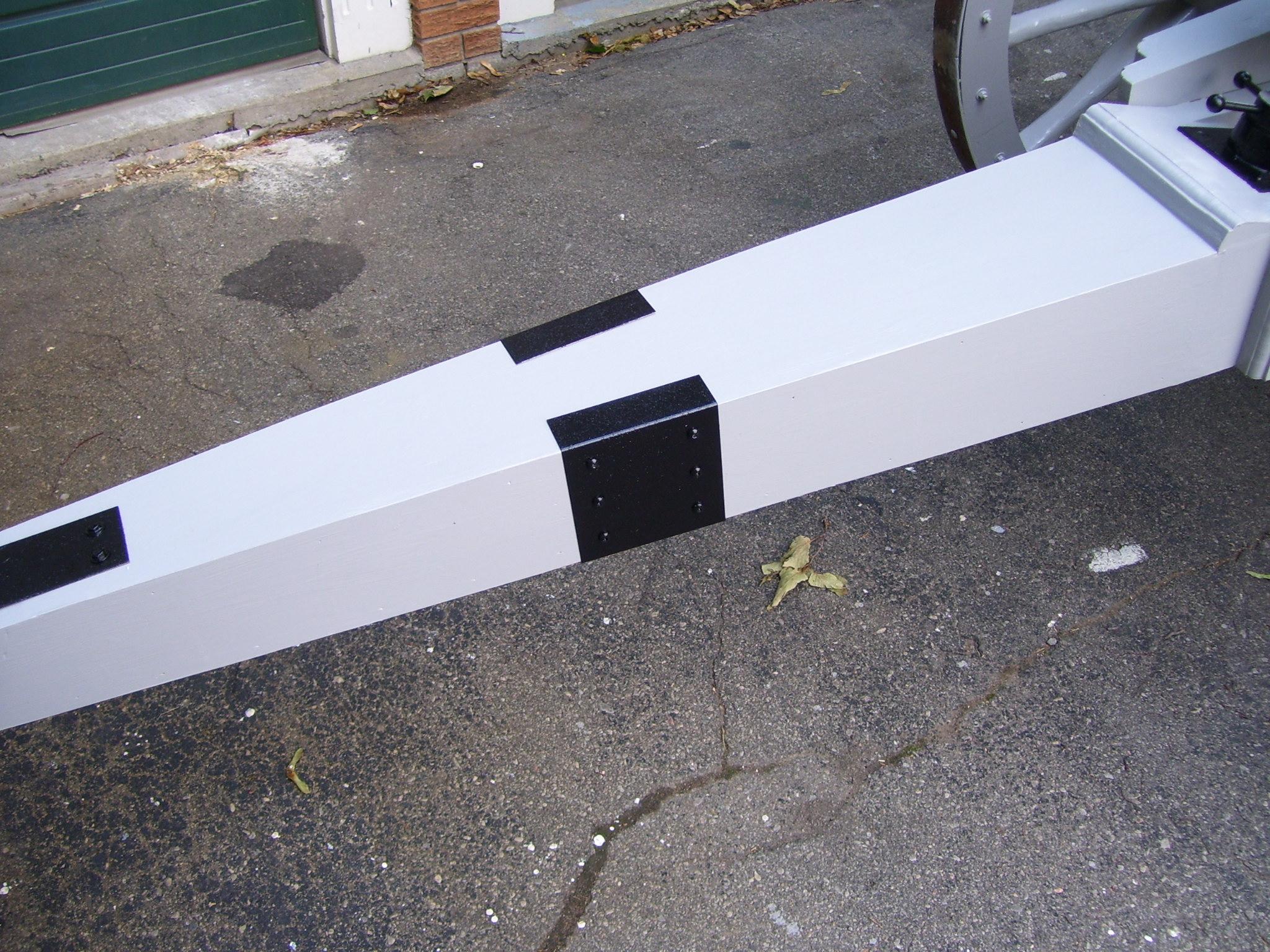
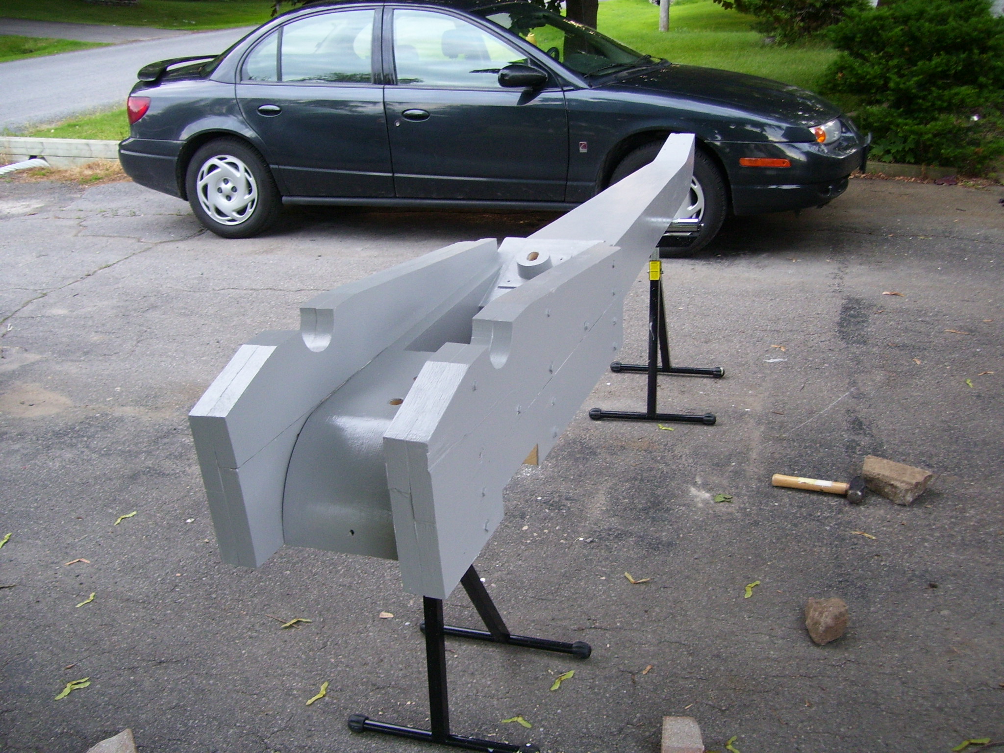
. The livery is artillery grey with black hardware.
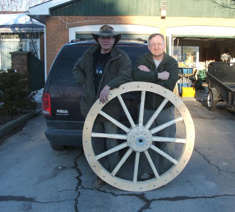
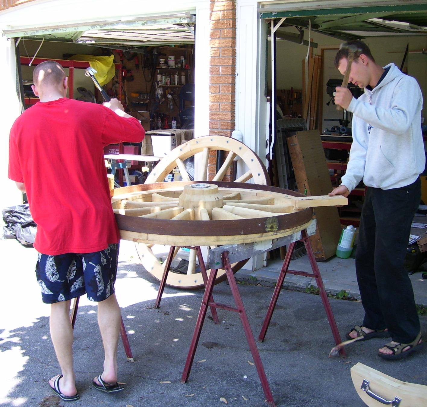
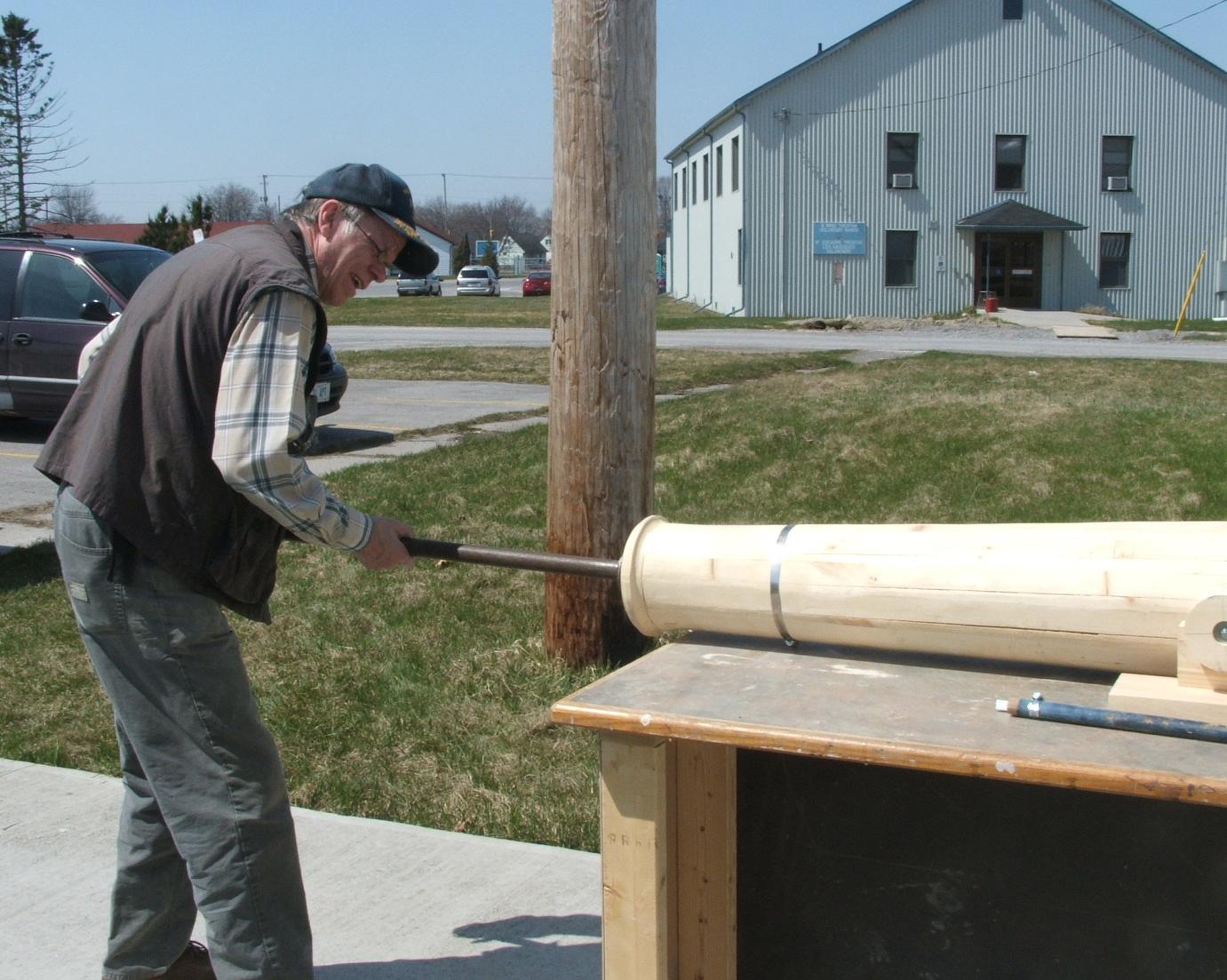
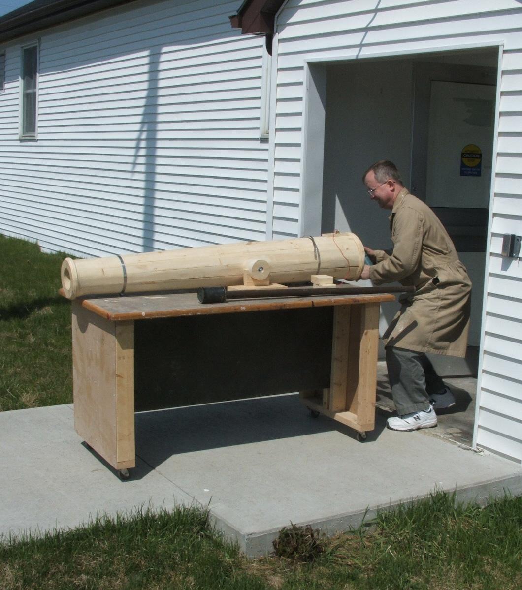
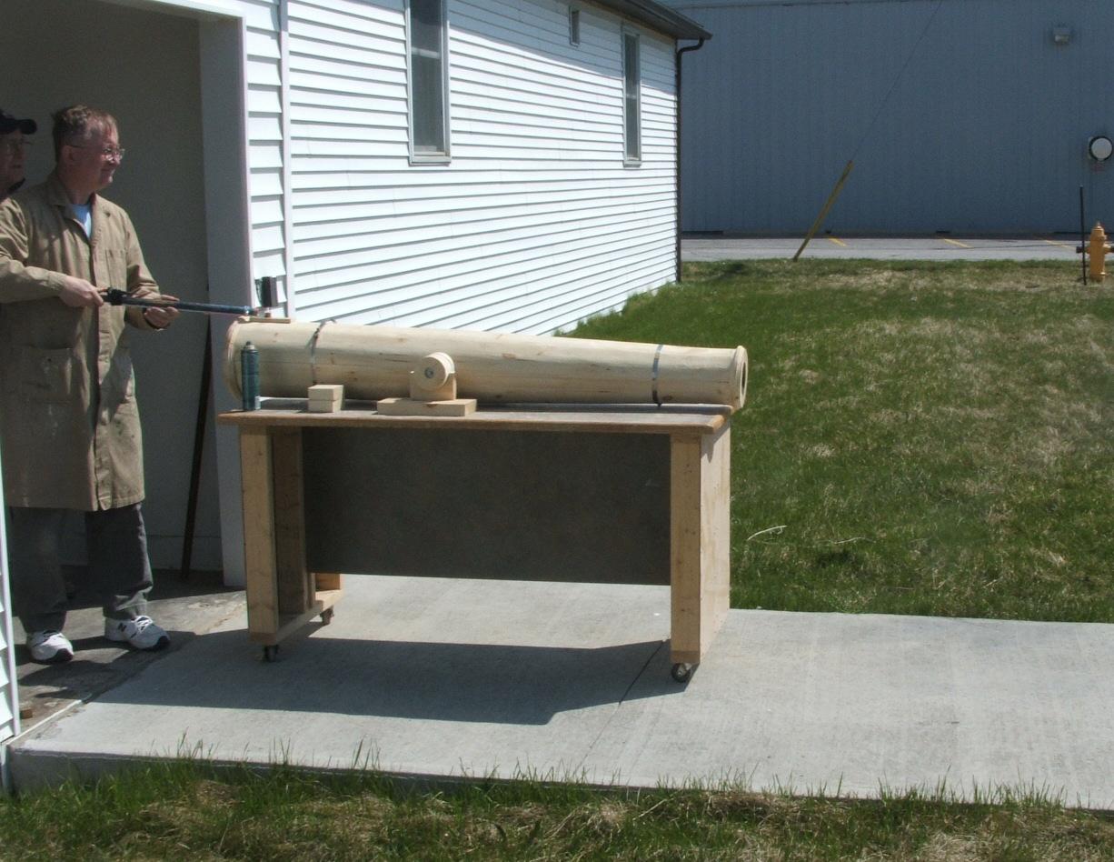
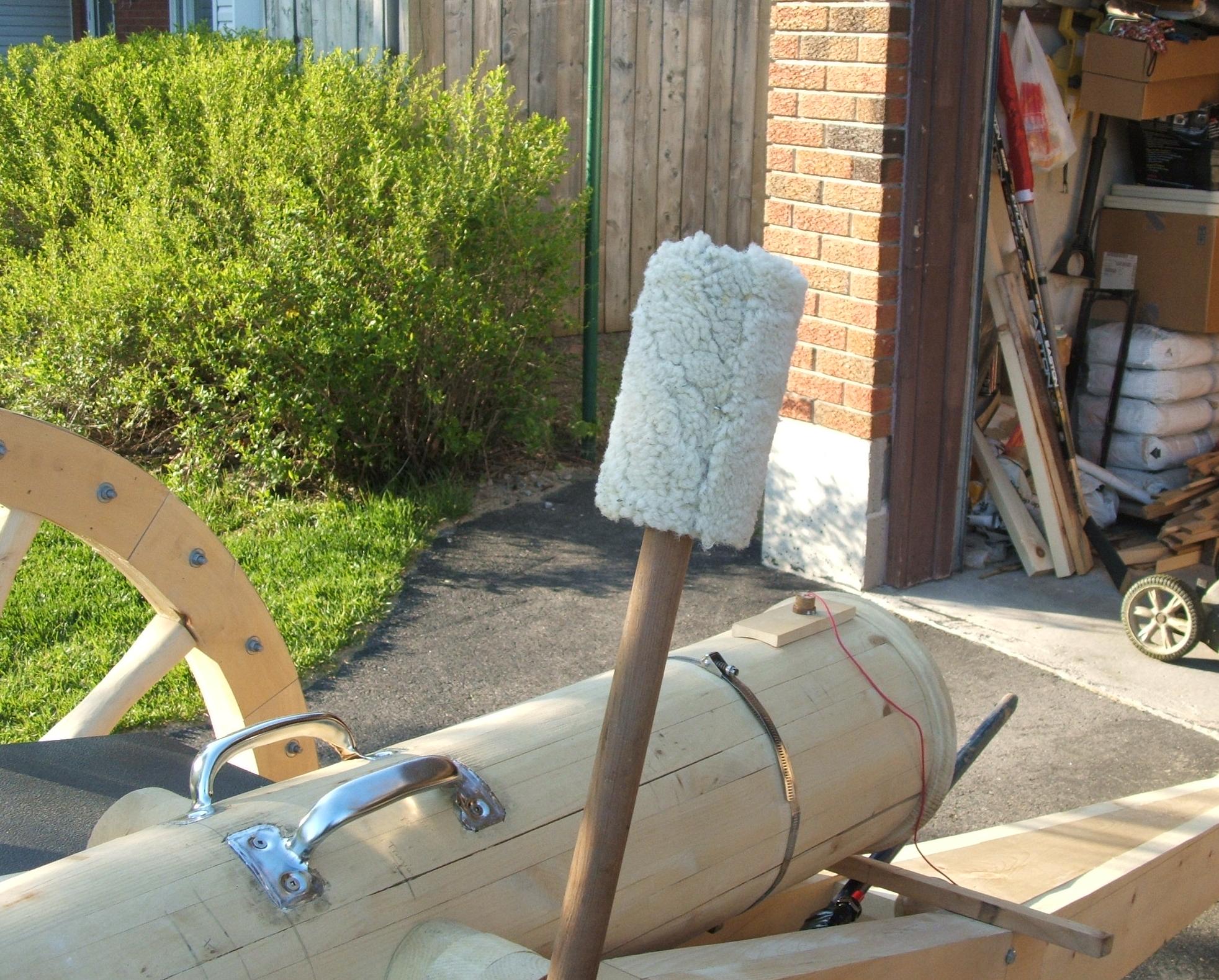
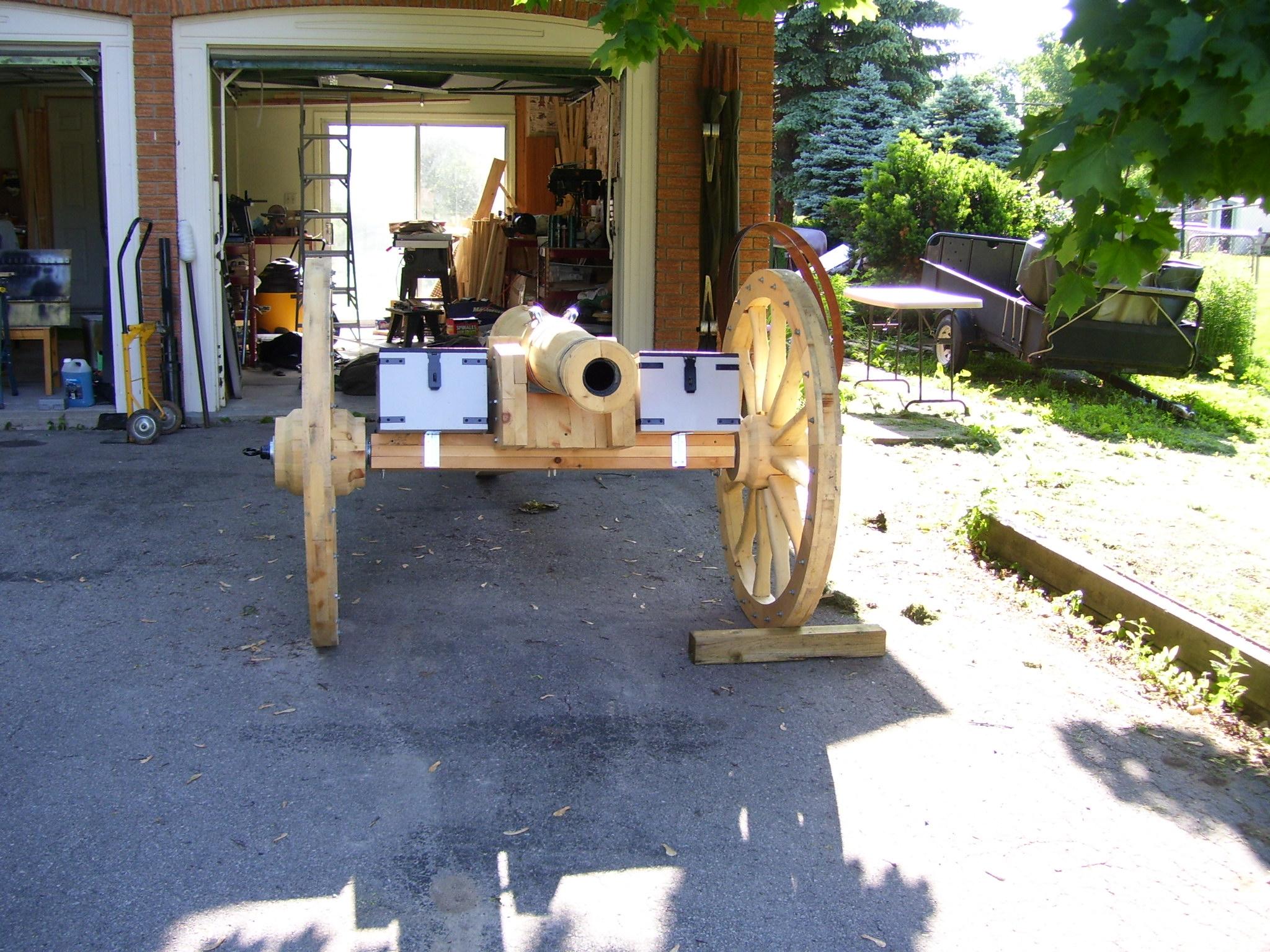
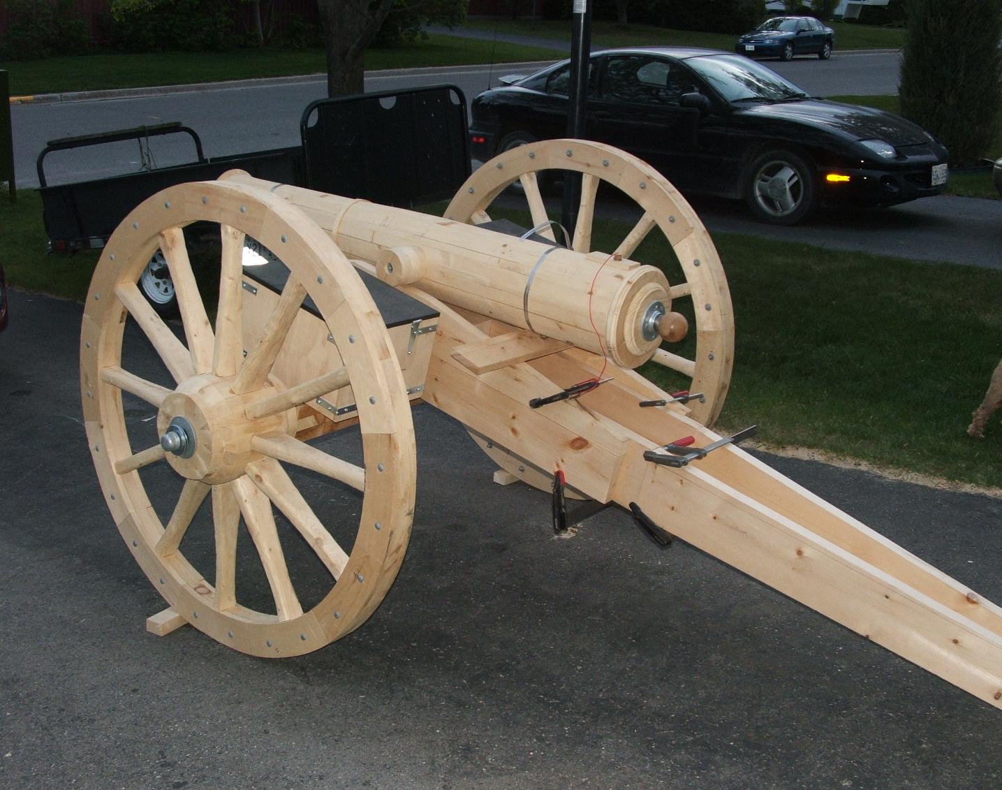
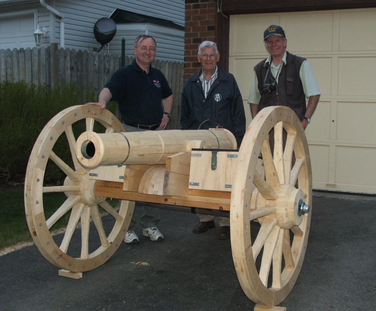
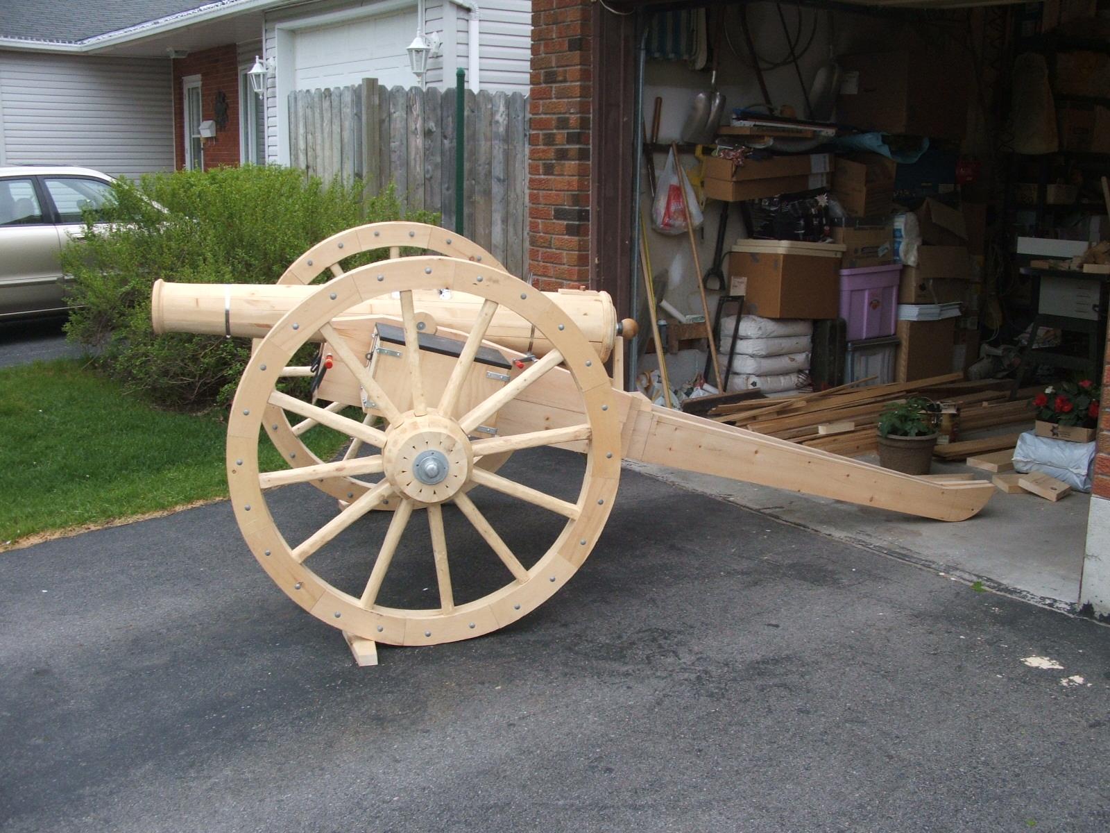
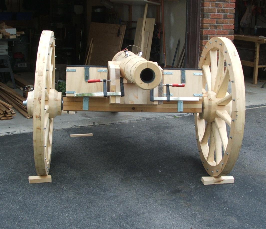
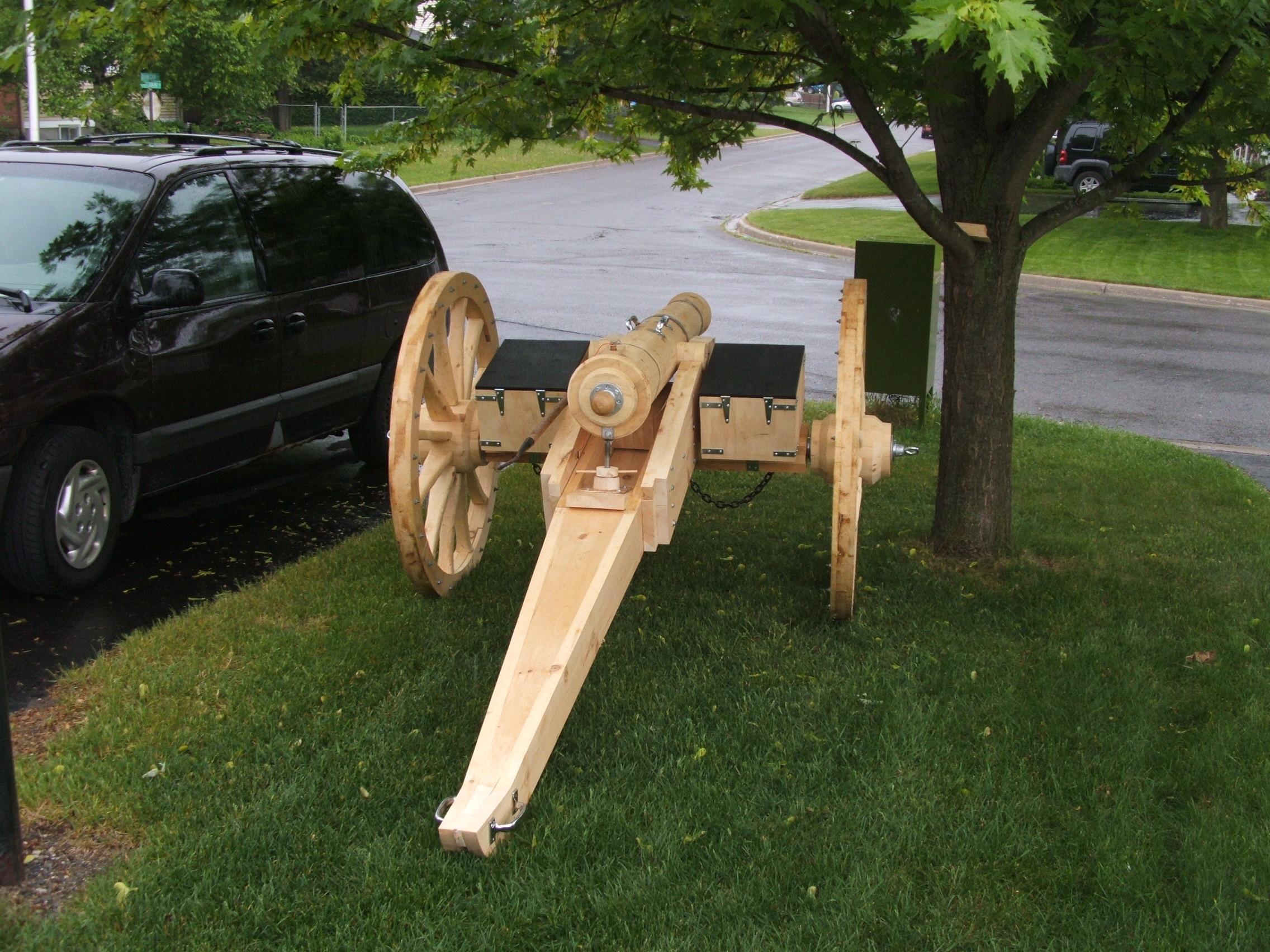
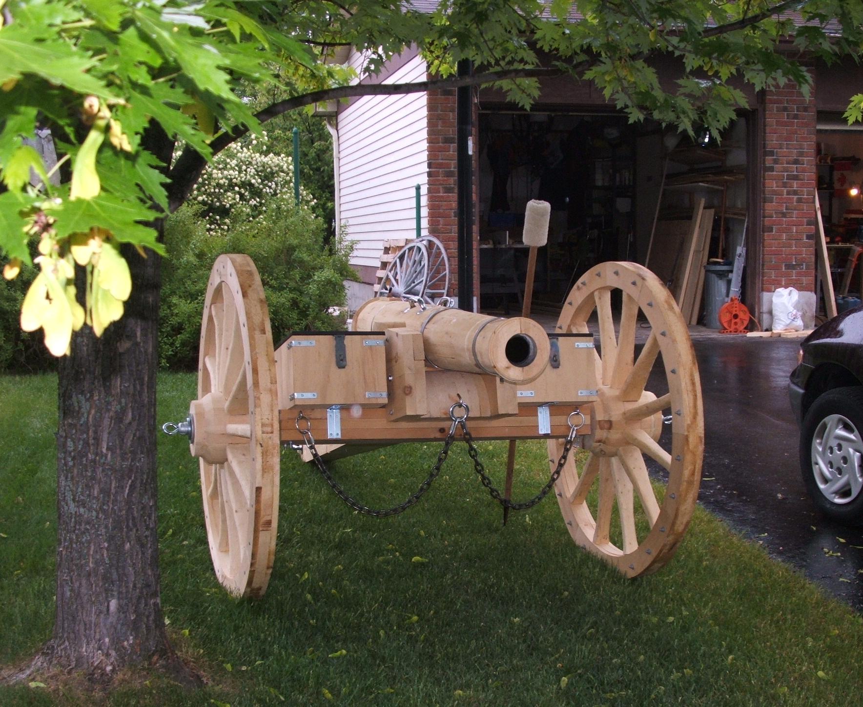
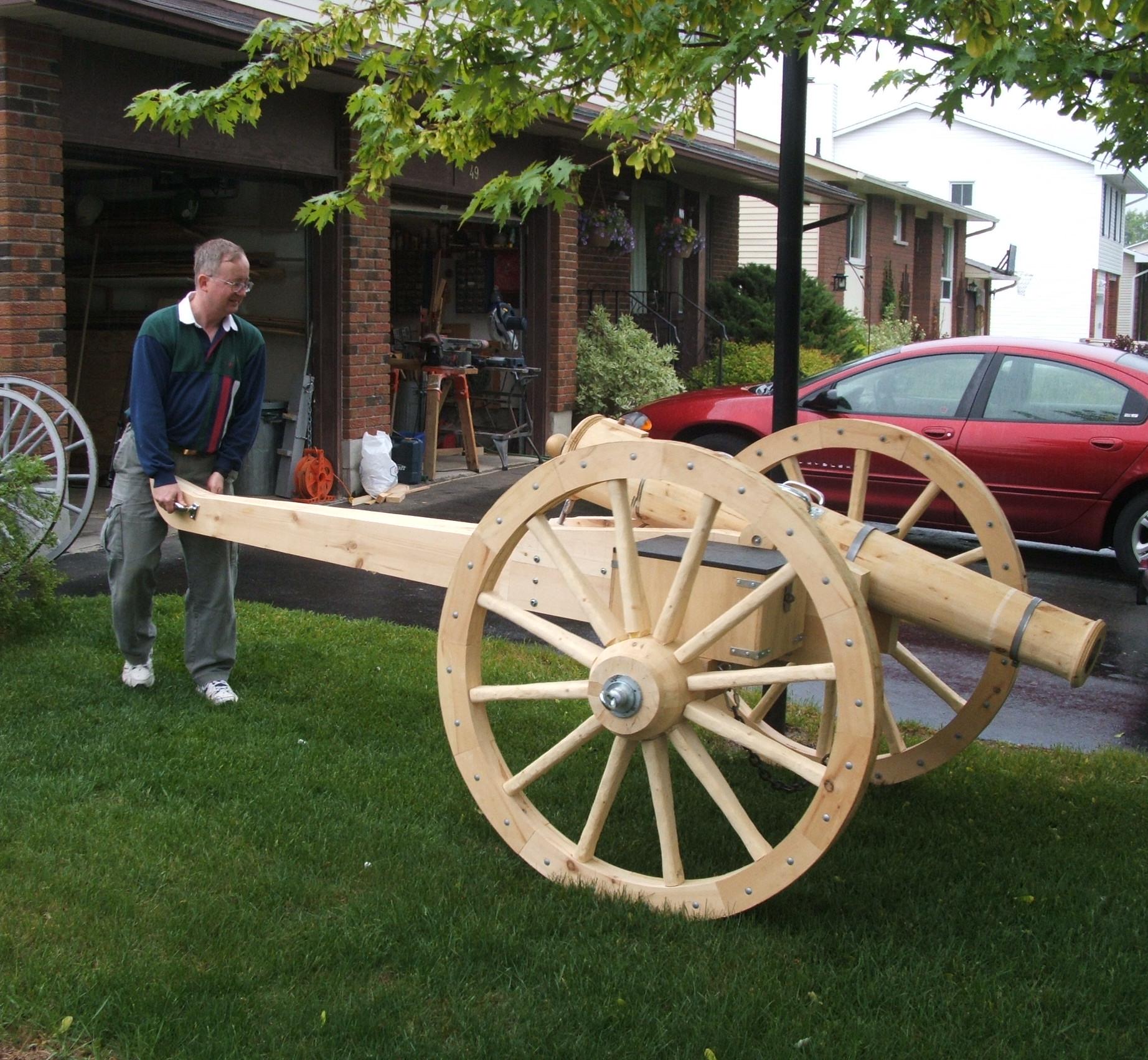
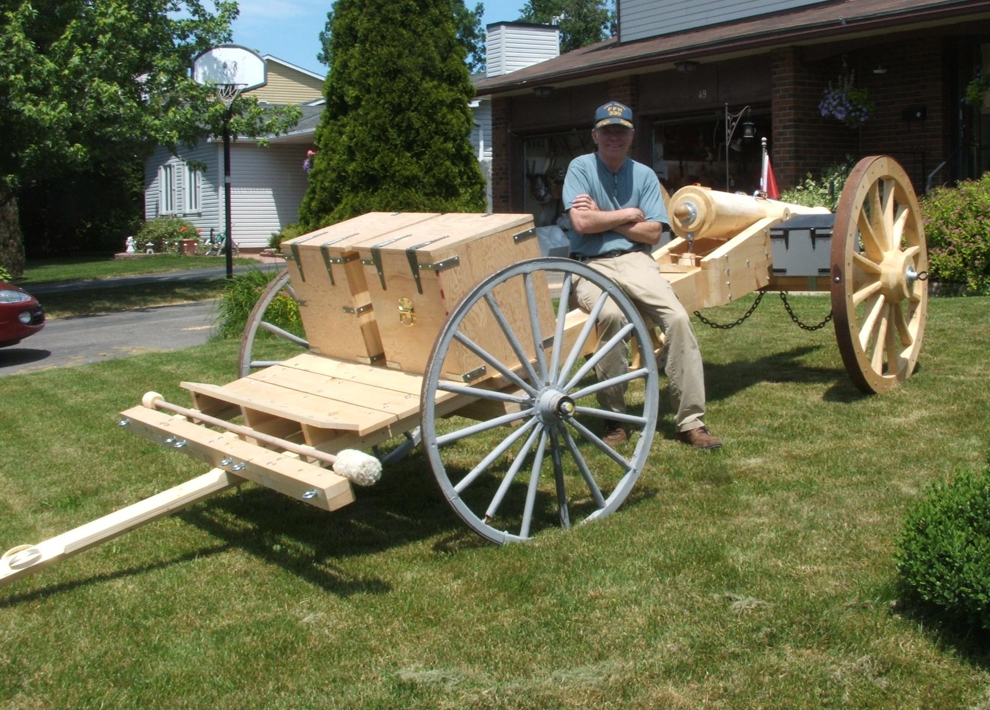
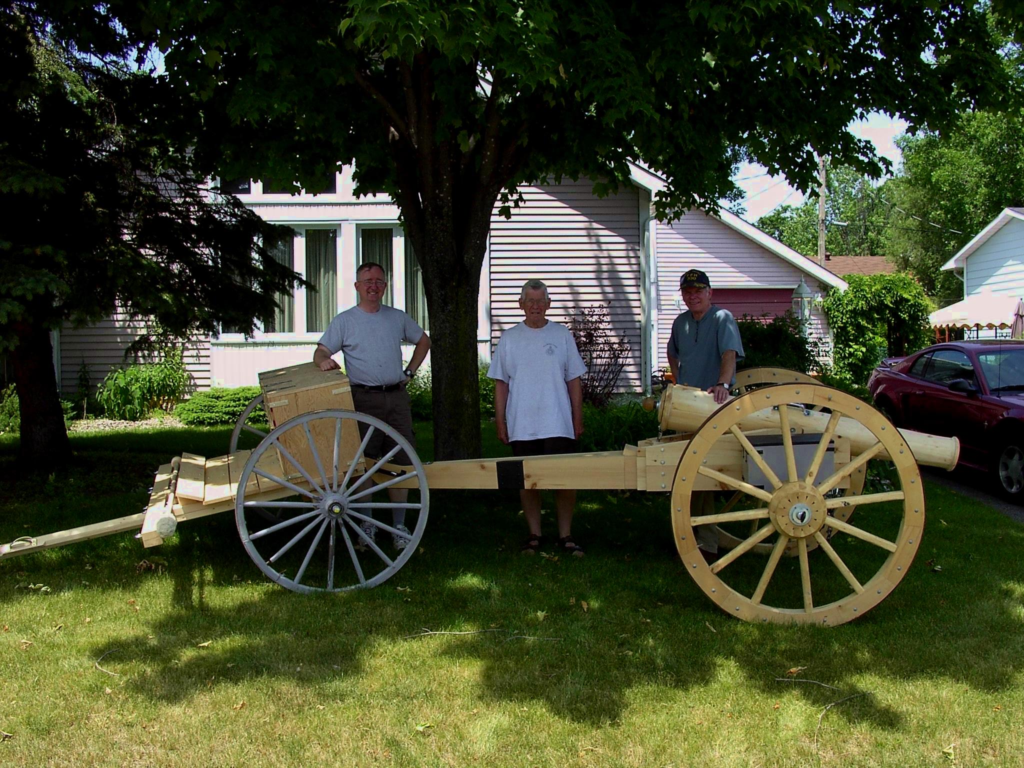
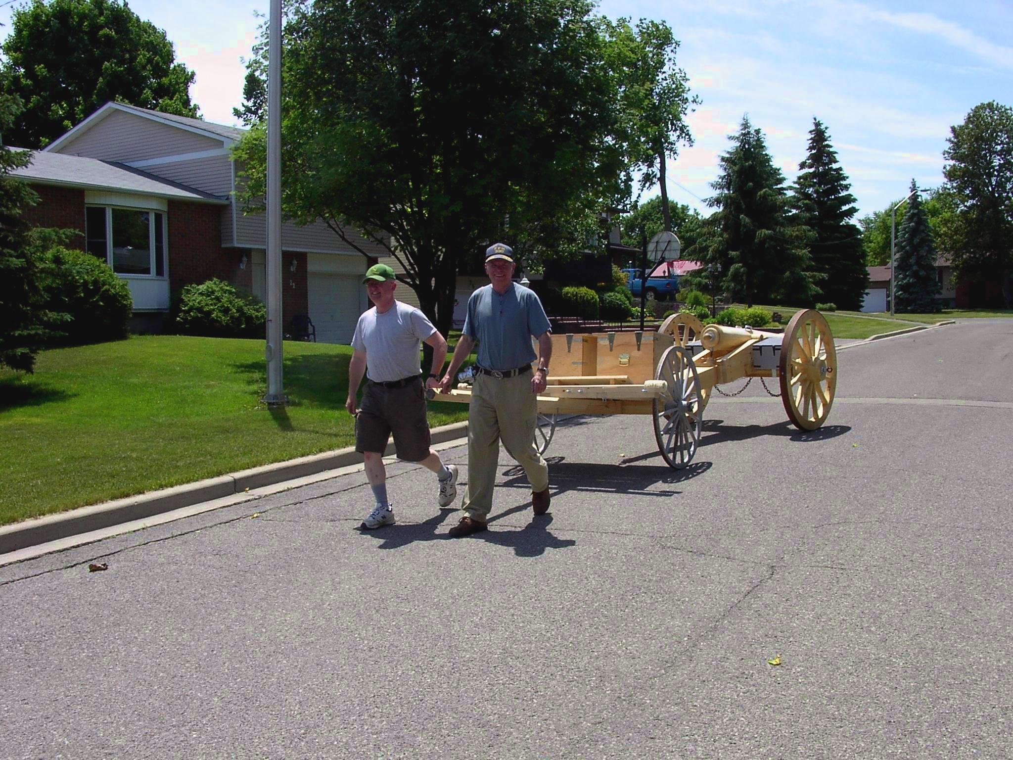
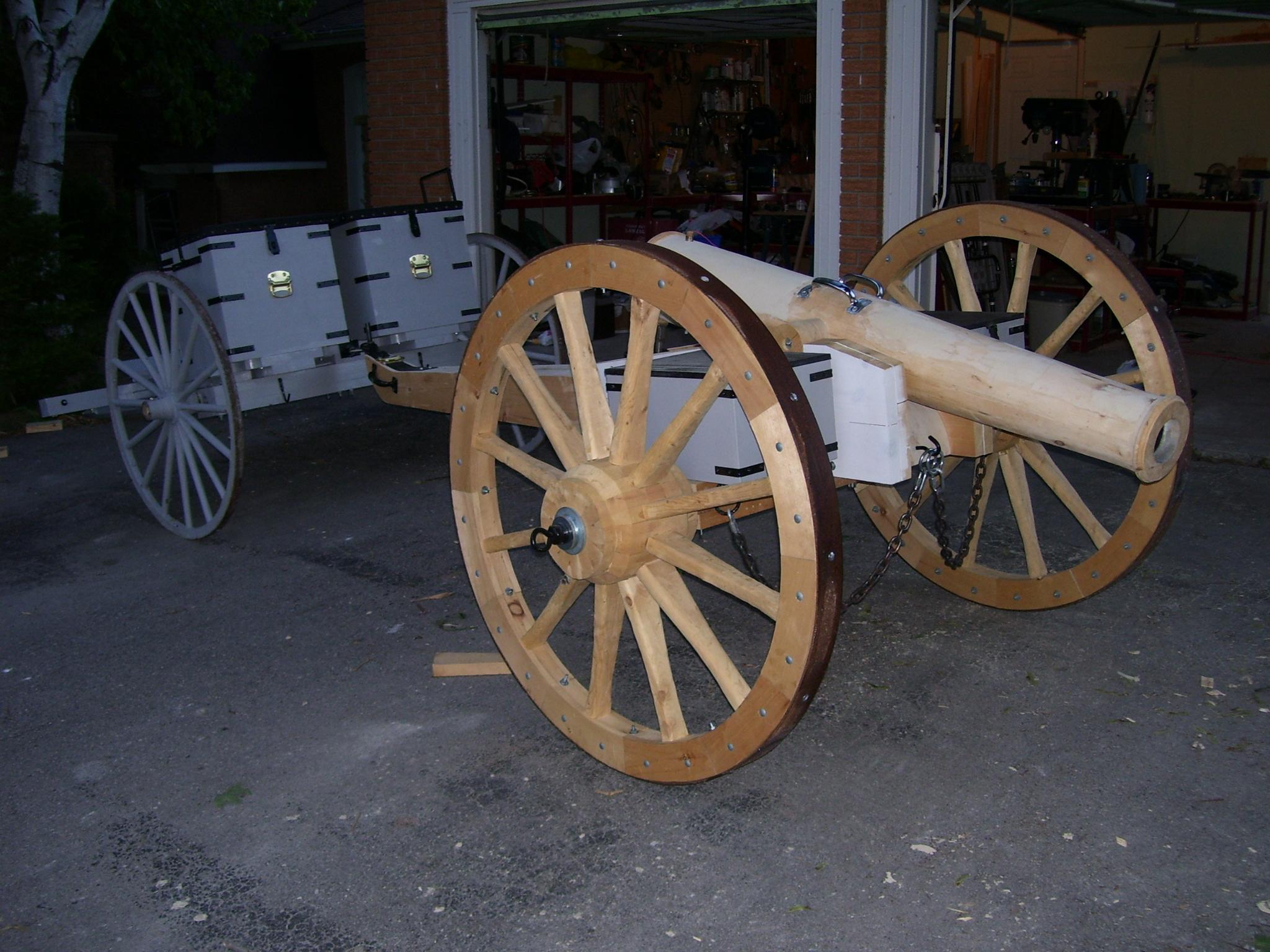
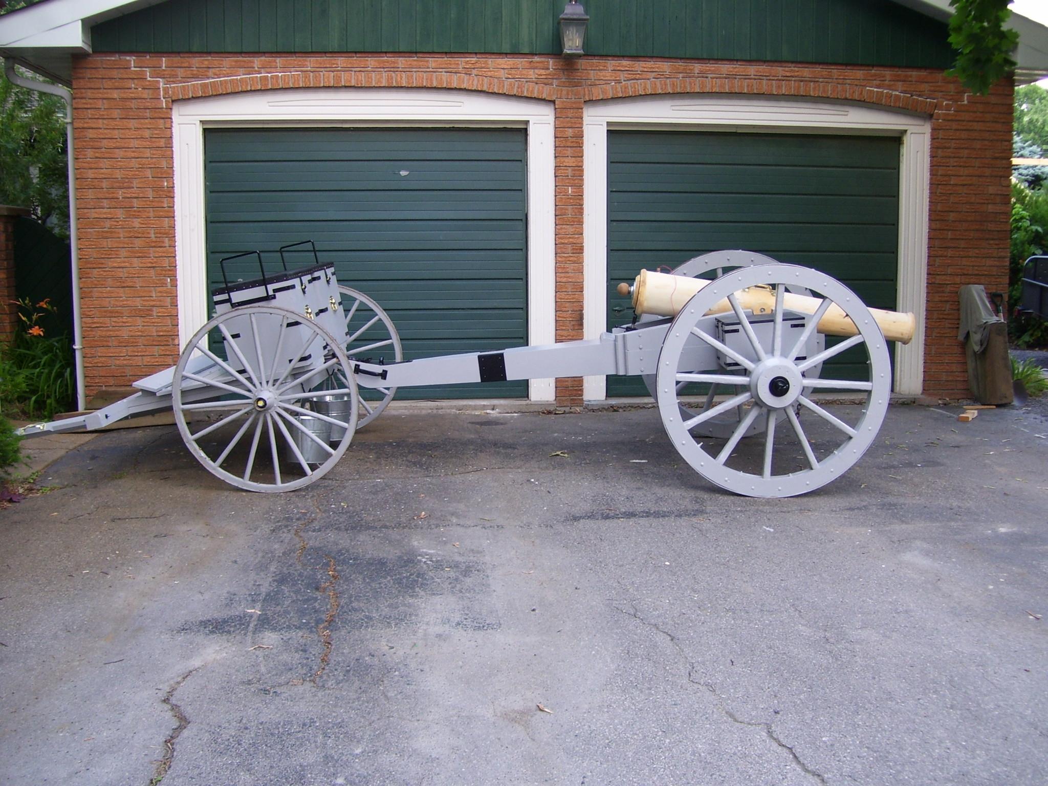
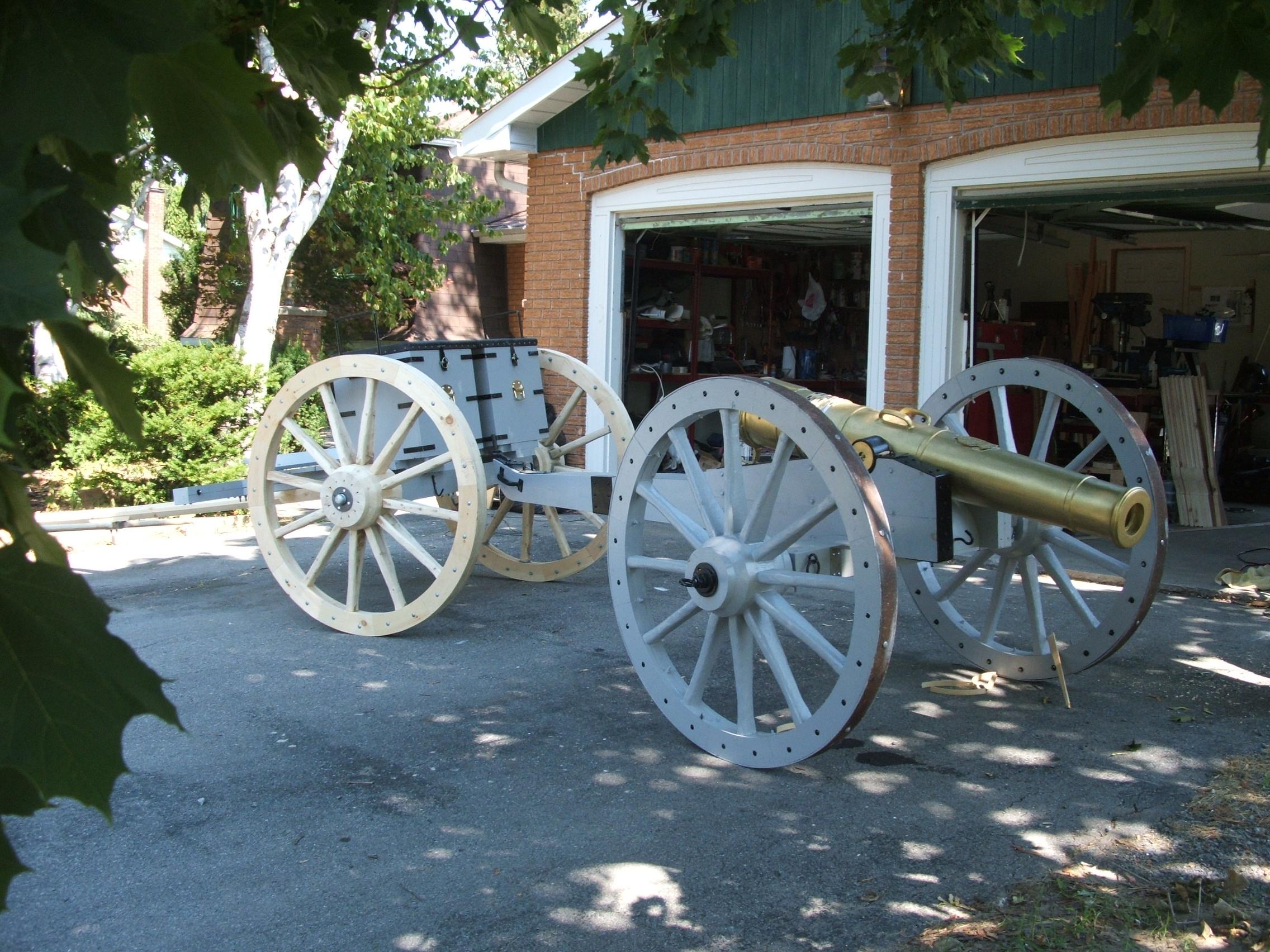
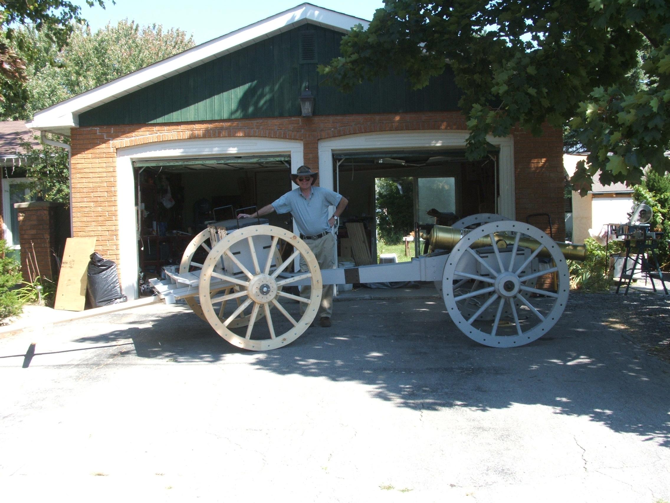
How
she looks…
And towards completion…
WARNING: The pictures here are intended to provide information to
scouting groups about building artillery for re-enactments. Scouting have
dedicated and thorough procedures for the operation of re-enactment artillery
in a safe manner. Users must become thoroughly familiar with these procedures
before charging and firing. This is a gun, not a toy, and to prevent injury, it
must be accorded respect at all times.
The gun can be damaged, or worst, burst, if fired with too much
propellant.
-
Use only the recommended hairspray & deodorant, and spray for no
more than the prescribed amount.
-
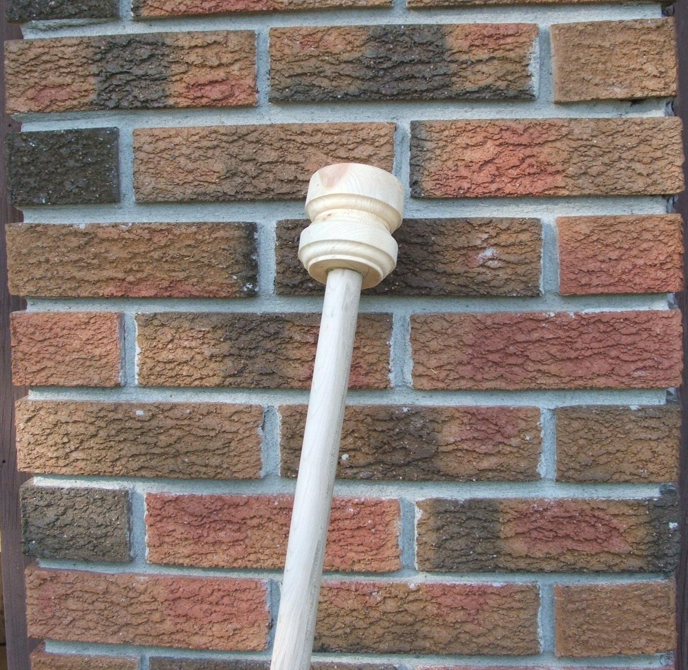
Use only a cloth for a wad, and do not jam it in so tight as it
cannot be ejected upon firing.
-
Do not fire a projectile from this gun under any circumstances.
-
Do not point the weapon at persons, animals or property.
![]()
All pages are copyrighted © 2001 Maxwell J. Toms. All
rights reserved.
Information in this document is subject to change without notice.
Trademarks or registered trademarks of any products or companies referred to
herein are property of their respective companies or mark holders.